
Grommet

a technology of grommet and spherical head, which is applied in the direction of multi-purpose tools, insulating bodies, basic electric elements, etc., can solve the problem of time-consuming work

Active Publication Date: 2012-11-29
DAIWA KASEI IND CO LTD +1
View PDF7 Cites 22 Cited by
  • Summary
  • Abstract
  • Description
  • Claims
  • Application Information

AI Technical Summary

Benefits of technology

[0008]For example, in one aspect of the present invention, a grommet configured to seal an insertion hole formed in a panel into which a pipe is inserted may include a base that is configured to be connected to the insertion hole, a boot that is integrally formed in the base and has a thinned wall thickness, and at least one rib that is formed in the boot. The boot has a truncated cone-shaped main portion having an insertion bore into which the pipe can be inserted, and a connecting portion that is folded back from a circumferential periphery of the main portion via a folded back portion and is connected to the base. The at least one rib is formed in the main portion and the connecting portion while straddling the folded back portion, so as to restrict the main portion from being axially displaced relative to the base.
[0009]According to the aspect of the invention, even when the connecting portion of the boot is applied with a force in a direction to unfold or stretch the folded back portion thereof due to a frictional force produced between the pipe and the insertion bore or interference or contact of the main portion with a projected portion that may be inherently formed in the pipe, the main portion can be prevented from being axially displaced relative to the base by the at least one rib that is formed in the main portion. As a result, when the grommet is attached to the insertion hole, the folded back portion of the connecting portion can be prevented from being unfolded or stretched, so that the main portion can be prevented from being held while it is projected from the base. That is, when the grommet is attached to the insertion hole, the main portion can be automatically positioned and held within the base. Therefore, the grommet can be easily and reliably attached to the insertion hole by simply pressing the base toward the insertion hole without additional work. Thus, the grommet can be quickly attached to the insertion hole. This means that working efficiency of a grommet attaching operation can be increased.

Problems solved by technology

This work is time-consuming.

Method used


Image

  • Grommet
  • Grommet
  • Grommet

Examples


Embodiment Construction

[0025]Next, a representative embodiment of the present invention will be described with reference to FIGS. 1(A) to 6.

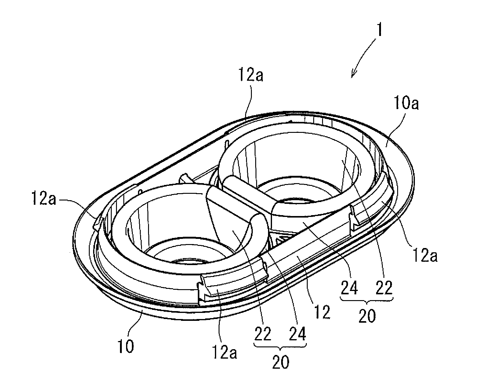
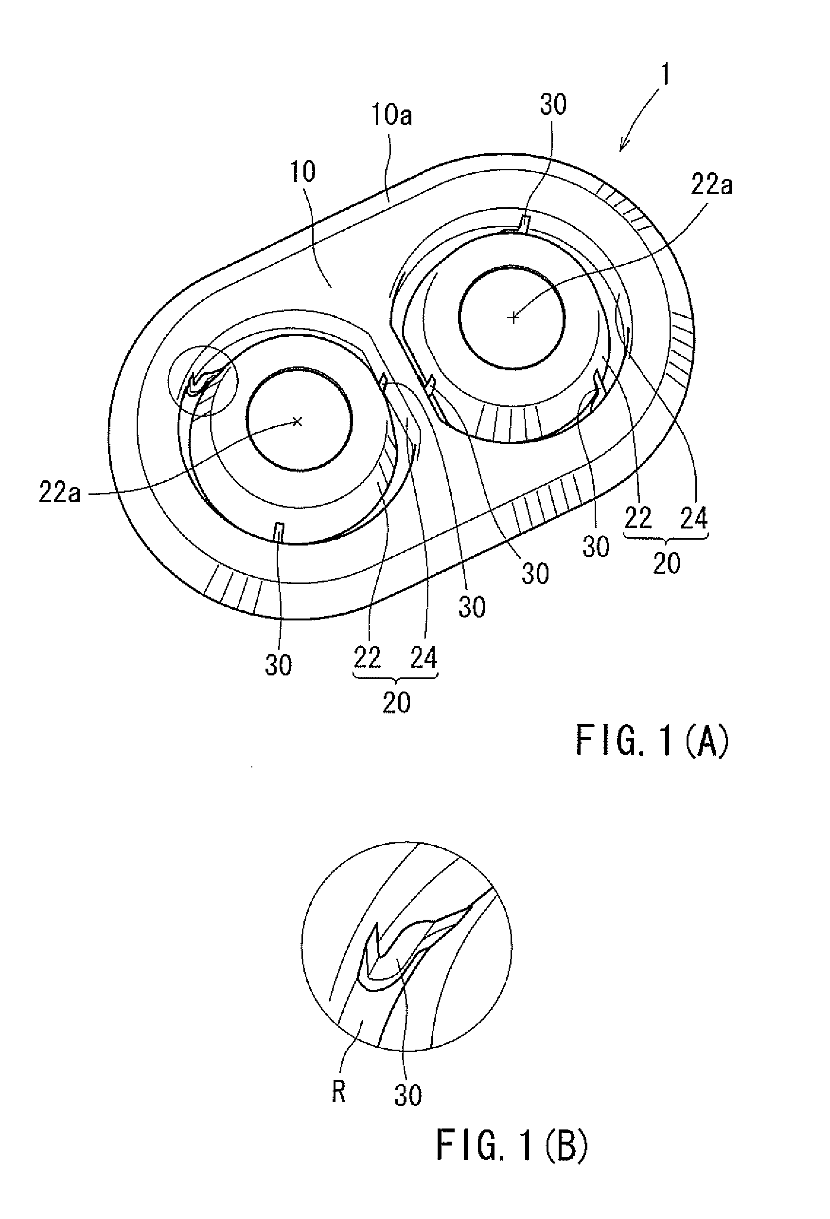
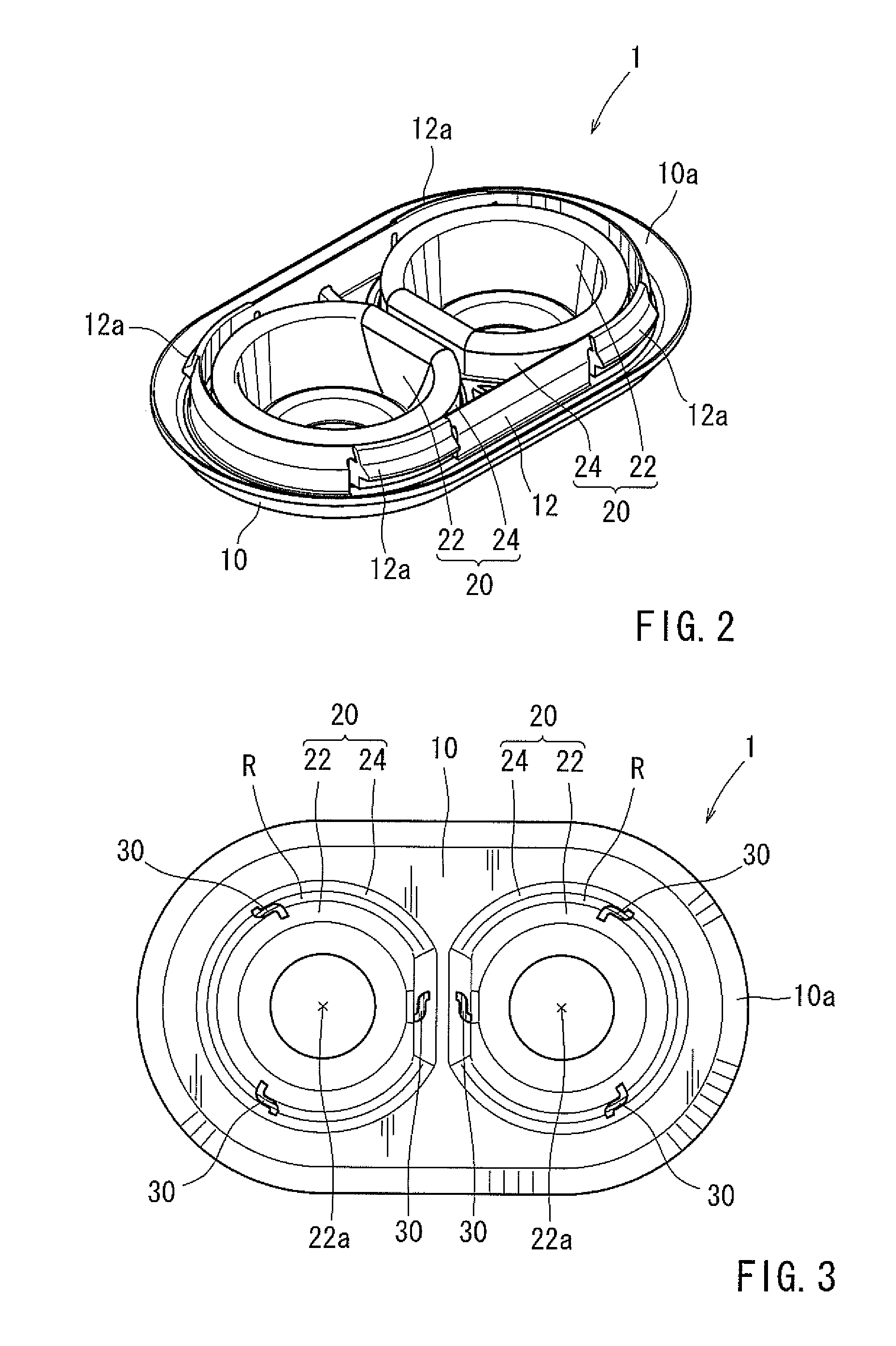
[0026]A representative grommet 1 is shown in FIGS. 1(A) to 3. Further, the grommet 1 is intended to be attached to an insertion hole 42 formed in a panel 40 in order to seal the insertion hole 42 into which at least one (two in this embodiment) pipes 50 are inserted (FIGS. 4(A) to 6). An example of the panel 40 is a compartment panel (a dash panel) that isolates a vehicle cabin (not shown) from an engine compartment (not shown). Conversely, examples of the pipes 50 are low-pressure pipes and high-pressure pipes used in an air-conditioning device of a vehicle.

[0027]As shown in FIGS. 1(A) to 3, the grommet 1 may mainly include a plate-shaped base 10 that is configured to be introduced into an insertion hole 42, and at least one (two in this embodiment) boots 20 that are integrally formed in the base 10 and have a thinned wall thickness. The base 10 may have an annular l...


PUM


Abstract

A grommet configured to seal an insertion hole formed in a panel into which a pipe is inserted may include a base that is configured to be connected to the insertion hole, a boot that is integrally formed in the base and has a thinned wall thickness, and at least one rib that is formed in the boot. The boot has a truncated cone-shaped main portion having an insertion bore into which the pipe can be inserted, and a connecting portion that is folded back from a circumferential periphery of the main portion via a folded back portion and is connected to the base. The at least one rib is formed in the main portion and the connecting portion while straddling the folded back portion, so as to restrict the main portion from being axially displaced relative to the base.

Description

BACKGROUND OF THE INVENTION[0001]1. Field of the Invention[0002]The present invention relates to a grommet. More particularly, the present invention relates to a grommet that is attached to an insertion hole formed in a panel (e.g., a vehicle body panel) in order to seal the insertion hole into which a pipe is inserted.[0003]2. Description of Related Art[0004]A known grommet of this type is taught by, for example, Japanese Laid-Open Patent Publication Number 2004-312927. As shown in FIGS. 7 to 11, the grommet 101 has a base 110 and boots 120. The base 110 is configured to be introduced into an insertion hole 142 formed in a panel 140. Each of the boots 120 is integrally formed in the base 110 and has a thinned wall thickness. The boots 120 are composed of truncated cone-shaped main portions 122 and connecting portions 124. The main portions 122 respectively have insertion bores 122a into which pipes 150 are inserted. The connecting portions 124 are respectively folded back from circ...

Claims


Application Information

Patent Timeline
Patent Type & Authority Applications(United States)
IPC IPC(8): F16L5/02
CPCF16L5/10F16L5/14Y10T16/088Y10T16/05Y10T16/063
Inventor IWAHARA, TOSHIOSUGIYAMA, TAKAHIROOKAICHI, KEIJIKAMIGASHIMA, HAYATO
Owner DAIWA KASEI IND CO LTD
Learn More