Unit for separating a pre-cut substrate positioned downstream from a cutting unit

Active Publication Date: 2012-11-22
BOBST MEX SA
View PDF13 Cites 0 Cited by
  • Summary
  • Abstract
  • Description
  • Claims
  • Application Information

AI Technical Summary

Benefits of technology

[0013]A main objective of the present invention consists in developing a unit designed to separate a pre-cut substrate into a plurality of separate sub-substrates positioned downstream of a cutting unit for a packaging production machine. A second objective is to optimize the accuracy of the separation of the pre-cut substrates into separate individual sub-substrates. A third objective is to produce a separator unit enabling rapid adaptation to any new job. A fourth objective is to provide a separator unit provided with means for fast and easy adjustment of the number, angle and position of the ramps. A further fifth objective is that of obtaining a separator unit enabling the drawbacks of the prior art to be avoided. A further object is that of providing a packaging production machine with a cutting unit, a waste stripping unit and a separator unit.
[0018]upstream locking means and downstream locking means able to maintain each of these conveyor ramps in a locked positioned relative to these upstream transverse guide means and said downstream transverse guide means.
[0022]In other words, the separator unit enables facilitated adjustment of the position and the orientation of the conveyor ramps thanks to a single mobile element. The separator unit also enables adjustment of the position and the orientation of one or more conveyor ramps with the other ramps remaining in their locked state. Because of the arrangement of the mobile element, it is possible to adjust the position of a single ramp without taking into account the position of the other ramps. The transverse movement and the angle of divergence of the ramps are thus effected ramp by ramp.

Problems solved by technology

This operation is laborious and time-consuming, however.
The downtime of the separator and thus of the whole of the machine used during manual adjustment of each of the ramps is reflected in the end in a serious loss of production.
Moreover, in the above document, it is not possible to move the conveyor ramps laterally relative to each other.
Moreover, it is impossible to move a plurality of ramps at the same time, because the optical system is not able to identify a plurality of pin positions at the same time.
This is another drawback, because accidental movement of a correctly positioned conveyor ramp could occur during adjustment of the other conveyor ramps, leading to incorrect positioning of the boxes within the separator unit.

Method used


Image

  • Unit for separating a pre-cut substrate positioned downstream from a cutting unit
  • Unit for separating a pre-cut substrate positioned downstream from a cutting unit
  • Unit for separating a pre-cut substrate positioned downstream from a cutting unit

Examples


Embodiment Construction

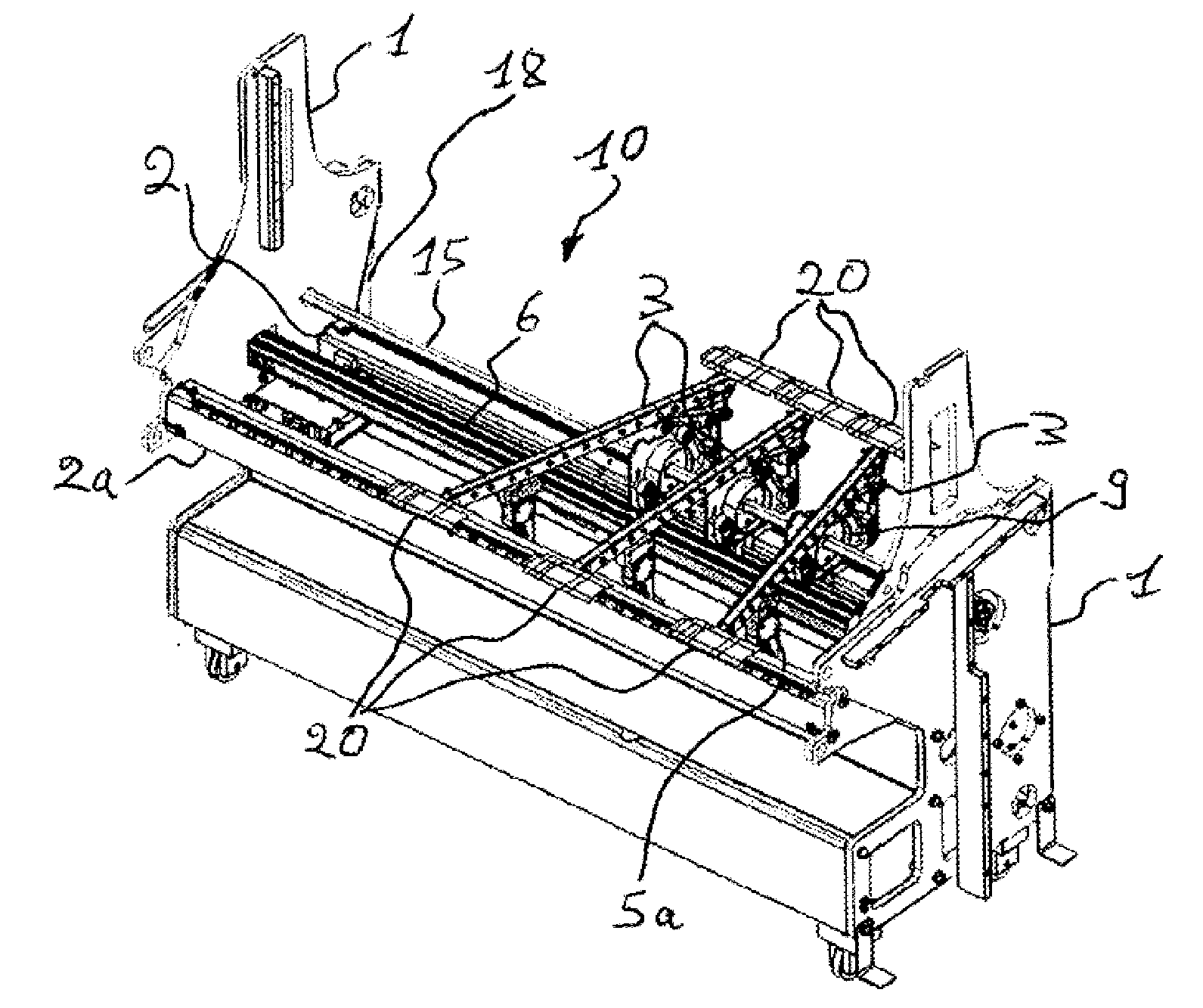
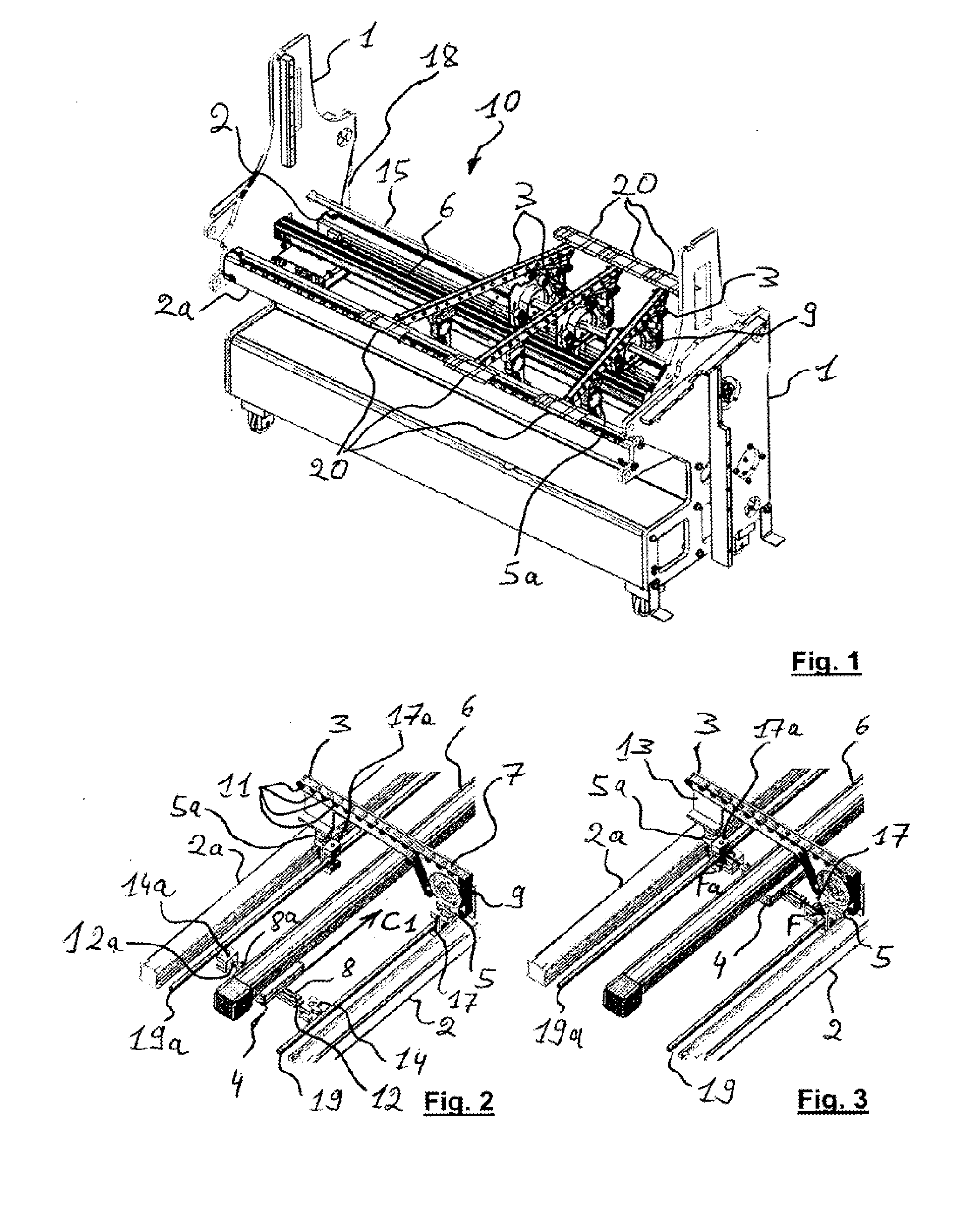
[0030]A separator unit 10 is positioned downstream of a cutting unit and a waste stripping unit in a packaging production machine (not shown). As FIG. 1 shows, the unit 10 enables separation of substrates, i.e. pre-cut blanks in this case, into sub-substrates, i.e. individual boxes 20 in this case. These blanks and thus these boxes 20 are made of cardboard, for example.

[0031]The unit 10 is designed to receive a stream of rows of adjacent boxes 20. In this embodiment, the boxes 20 leave the cutting unit still joined to each other by small bridges of material. The boxes 20 leave the separator unit 10 separated from each other.

[0032]The production machine may then include an alignment module (not shown) positioned downstream of the unit 10 to straighten the boxes 20 and place them along a plurality of longitudinal parallel lines. The boxes 20 are then shingled in a stream unit (not shown) positioned downstream of the unit 10.

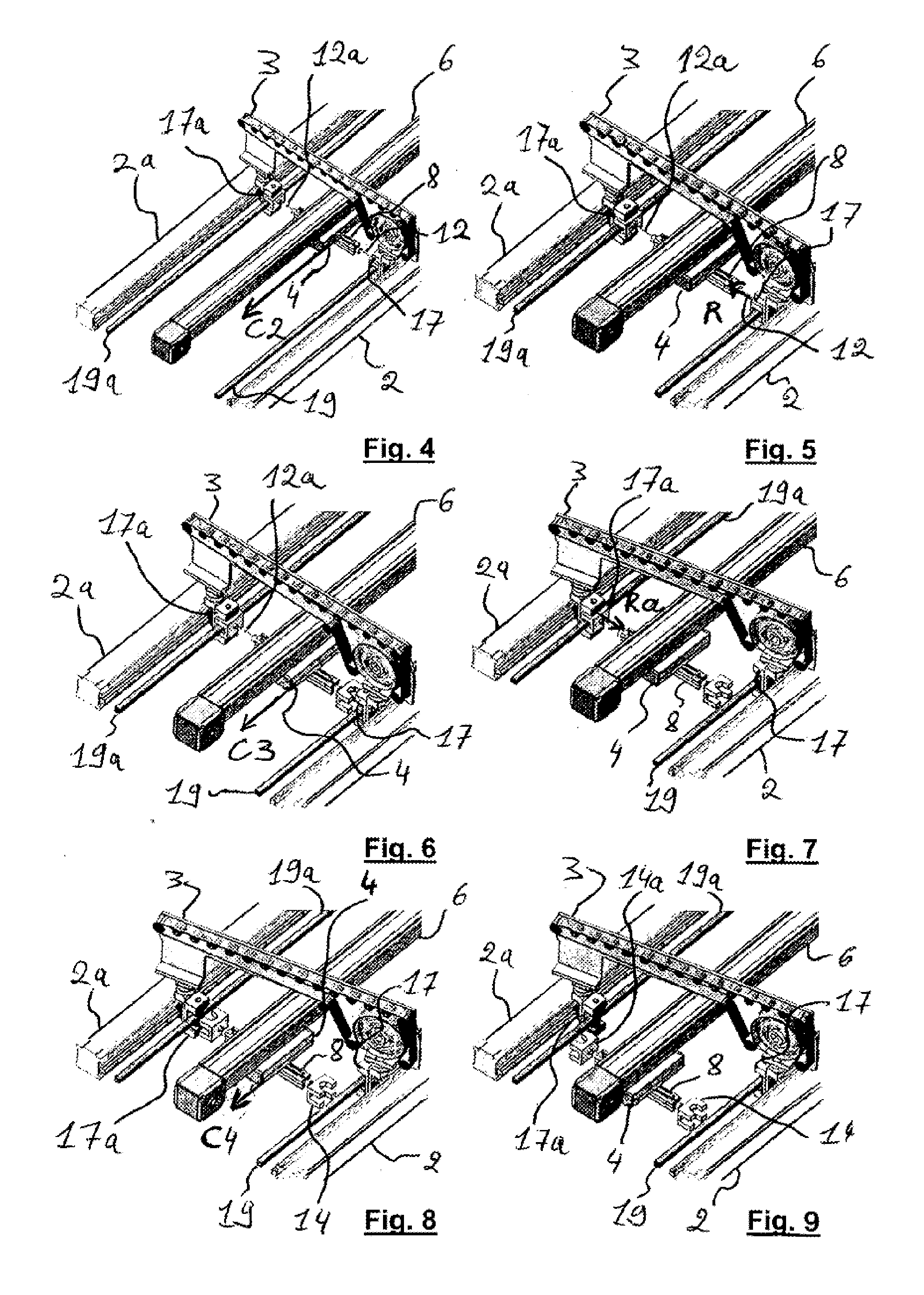
[0033]The blanks initially all move in the longitudinal direc...


PUM

PropertyMeasurementUnit
Areaaaaaaaaaaa

Abstract

A unit for separating a pre-cut-out substrate into a plurality of separate sub-substrates (20). The unit includes upstream (2) and downstream (2a) transverse guides; conveyor ramps, which convey the pre-cut-out substrate and the separate sub-substrates (20), the ramps are slidably and pivotably mounted on the guides (4). Upstream and downstream locks holds each ramp (3) in a locked position. A movable element supports upstream and downstream unlocking devices for engaging the upstream and downstream locking devices to release the ramps (3). Upstream and downstream grasping devices grasp and drive the ramps (3) along the upstream (2) and downstream (2a) guides to arrange the ramps in a fan-like configuration.

Description

[0001]The present invention concerns a unit for separating a pre-cut substrate into a plurality of separate sub-substrates. The separator unit is usable notably when positioned downstream of a cutting unit in a packaging production machine.[0002]A packaging production machine is designed for the fabrication of boxes that form packaging after folding and gluing. In this machine, an initial continuous plane substrate, such as a plane web of cardboard, is unwound and is printed by a print unit, itself constituted of sub-units in the form of printing units. The web is then transferred into a cutting unit. After cutting, the substrates or blanks obtained have waste areas that are eliminated in a waste stripping unit.[0003]A substrate or blank is composed of a plurality of sub-substrates or boxes. Depending on the type of cutting unit used, for example with a diecutting platen, the boxes are attached to each other by nicks. The nicks join two edges of a cutting line between two boxes and ...

Claims


Application Information

Patent Timeline
IPC IPC(8): B65G47/26B26D7/06B65G37/00
CPCB26D7/32B65G47/26B65H29/16B65H2301/351B65H2402/60B65H2511/20B65H2701/1764B65H2801/42Y10T83/202B65H2220/02B65H2220/04B65H2220/11B26D7/06
Inventor DITTLI, OSKAR
Owner BOBST MEX SA
Why Eureka
Try Eureka