Joint filler composition

a filler composition and composition technology, applied in the field of filler compositions, can solve the problems of shrinkage, cracks, and contraction of filler compositions, and achieve the effect of reducing shrinkage and satisfying workability

Active Publication Date: 2012-11-15
YOSHINO GYPSUM CO LTD
View PDF5 Cites 2 Cited by
  • Summary
  • Abstract
  • Description
  • Claims
  • Application Information

AI Technical Summary

Benefits of technology

[0018]One object according to one aspect of the present invention may be to provide a joint filler composition that may simultaneously enable coating of the joint filler composition with a satisfactory workability and sufficiently reduce shrinkage or the so-called depression.

Problems solved by technology

However, after the drying type joint filler composition is coated and dried, the joint filler composition contracts, and the so-called depression may occur.
The shrinkage of the joint filler composition may cause cracks to form.
However, even in the case of the setting type joint filler composition, when mixing water is absorbed by the undercoating before the joint filler composition undergoes the hydration setting, the joint filler composition coated at the joint part contracts and the shrinkage or the so-called depression occurs.
When the wall paper is adhered over the undercoatings having the joint part filled by the joint filler composition, the undulation underneath also appears on the wall paper and damages the external appearance of the wall paper.
The operation to coat and dry the joint filler composition again is a troublesome operation, and in addition, each single coating requires a corresponding drying time.
As a result, when the coating and drying of the joint filler composition need to be repeated, the time of completion is delayed.
However, a mixture amount of the hollow particles must be increased in order to reduce the shrinkage or the so-called depression, and the operation of manually coating the joint filler composition by a jig such as a finishing knife takes more time as the amount of the hollow particles increases.
The operation of coating the joint filler composition thus becomes more troublesome to perform.
For these reasons, the amount of the hollow particles mixed in the joint filler composition is desirably limited to a predetermined amount that does not considerably deteriorate the efficiency of coating the joint filler composition, and consequently, the shrinkage or the so-called depression may not be reduced sufficiently.
Therefore, according to the conventional joint filler compositions, it is difficult to simultaneously enable coating of the joint filler composition with a satisfactory workability and sufficiently reduce the shrinkage or the so-called depression.

Method used


Image

  • Joint filler composition
  • Joint filler composition
  • Joint filler composition

Examples


embodiments

[0042]Next, a description will be given of embodiments of the present invention and example embodiments, by referring to the drawings.

[0043]Example embodiments Emb1 through Emb4 were created with a mass ratio of materials forming a joint filler composition illustrated in FIGS. 1 through 4, by mixing these materials, in order to obtain a joint filler composition using the joint filler composition in accordance with one aspect of the present invention. FIG. 1 is a diagram illustrating the mass ratio of materials forming the joint filler composition in the example embodiment Emb1 and a first comparison example, and FIG. 2 is a diagram illustrating the mass ratio of materials forming the joint filler composition in the example embodiment Emb2 and a second comparison example. FIG. 3 is a diagram illustrating the mass ratio of materials forming the joint filler composition in the example embodiment Emb3 and a third comparison example, and FIG. 4 is a diagram illustrating the mass ratio of...

example embodiment emb1

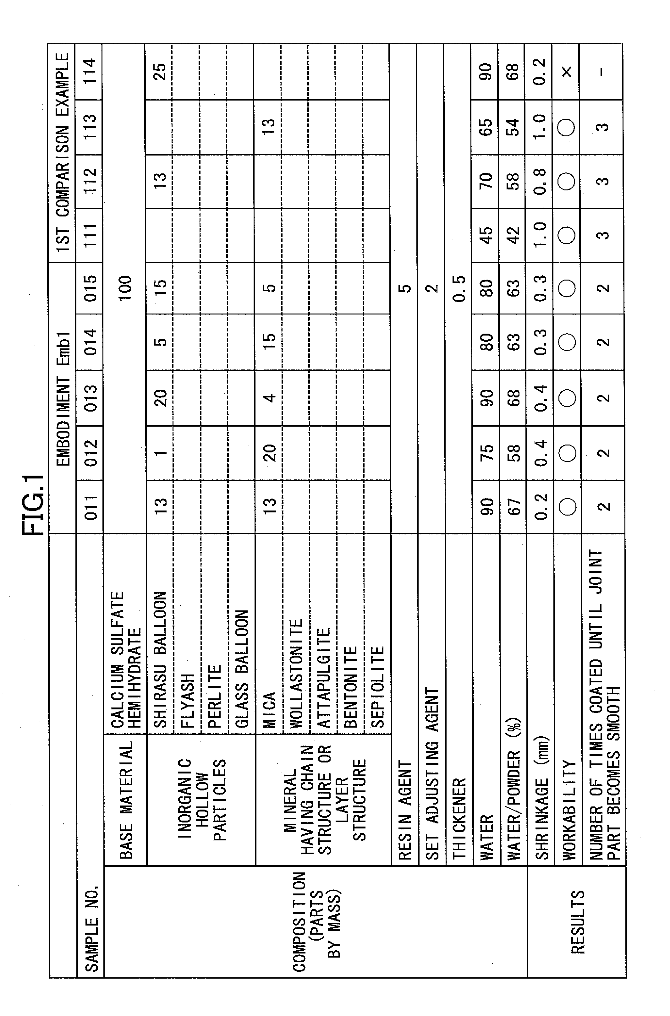
[0050]As described above, this example embodiment Emb1 used calcium sulfate hemihydrate as the base material. In addition, Shirasu Balloon was used as the inorganic hollow particles, and mica was used as the mineral having the chain structure or the layer structure. The amounts of the inorganic hollow particles and the mineral having the chain structure or the layer structure that are added were varied in order to evaluate the performance. Further, a first comparison example in which the inorganic hollow particles and the mineral having the chain structure or the layer structure are not added, or only one of the inorganic hollow particles and the mineral having the chain structure or the layer structure is added, were also evaluated. In FIG. 1 and each of FIGS. 2 through 4, 6 and 7 which will be described later, an entry that is blank indicates that the amount of the corresponding material that is added is zero (0).

[0051]In samples No. 011 through No. 015 of the example embodiment E...

example embodiment emb2

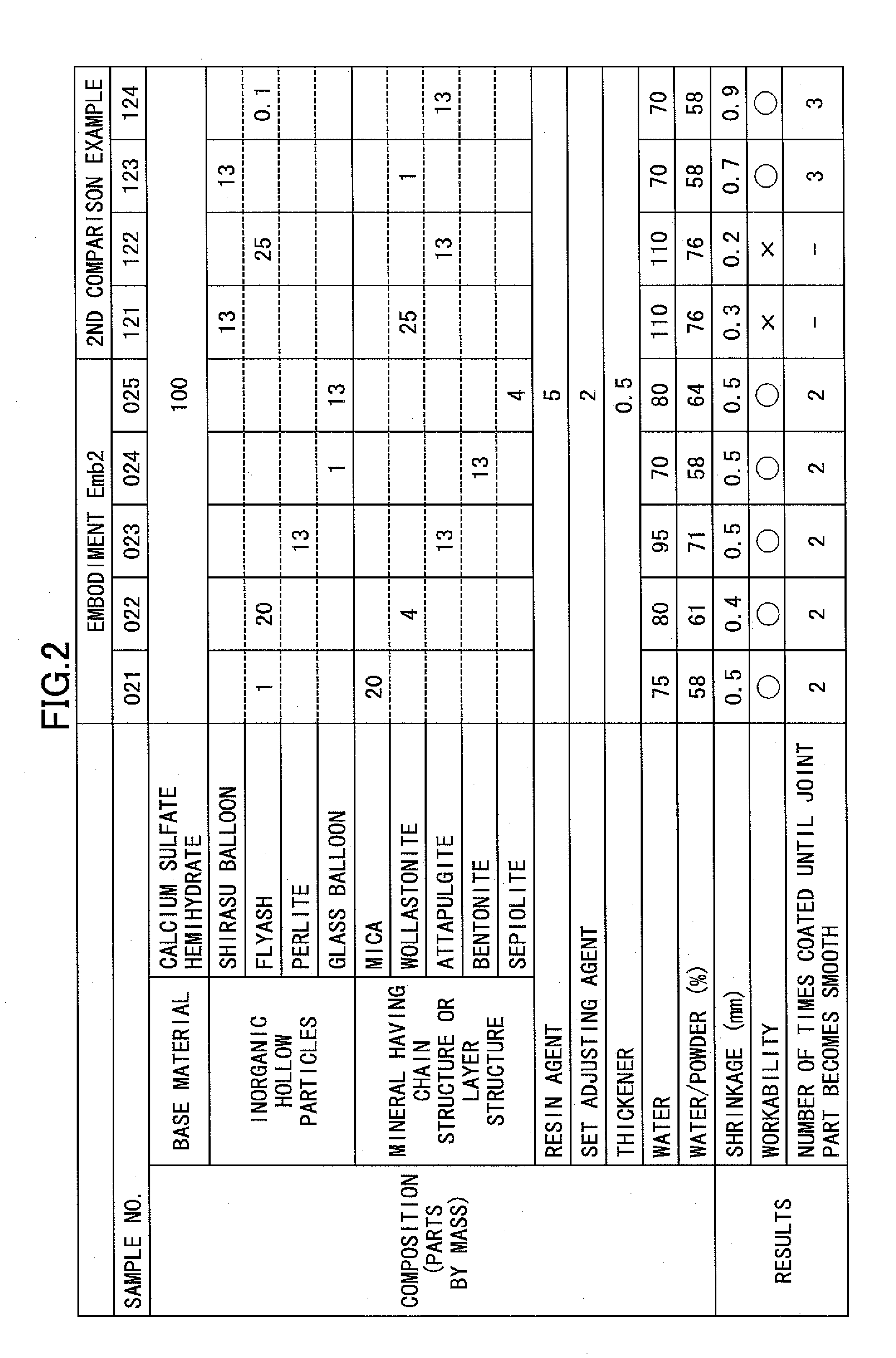
[0053]As described above, this example embodiment Emb2 used calcium sulfate hemihydrate as the base material, similarly as in the case of the example embodiment Emb1 described above. However, flyash, perlite or glass balloon was used as the inorganic hollow particles, and wollastonite, attapulgite, bentonite or sepiolite was used as the mineral having the chain structure or the layer structure. The amounts of the inorganic hollow particles and the mineral having the chain structure or the layer structure that are added were varied for a second comparison example in order to evaluate the performance.

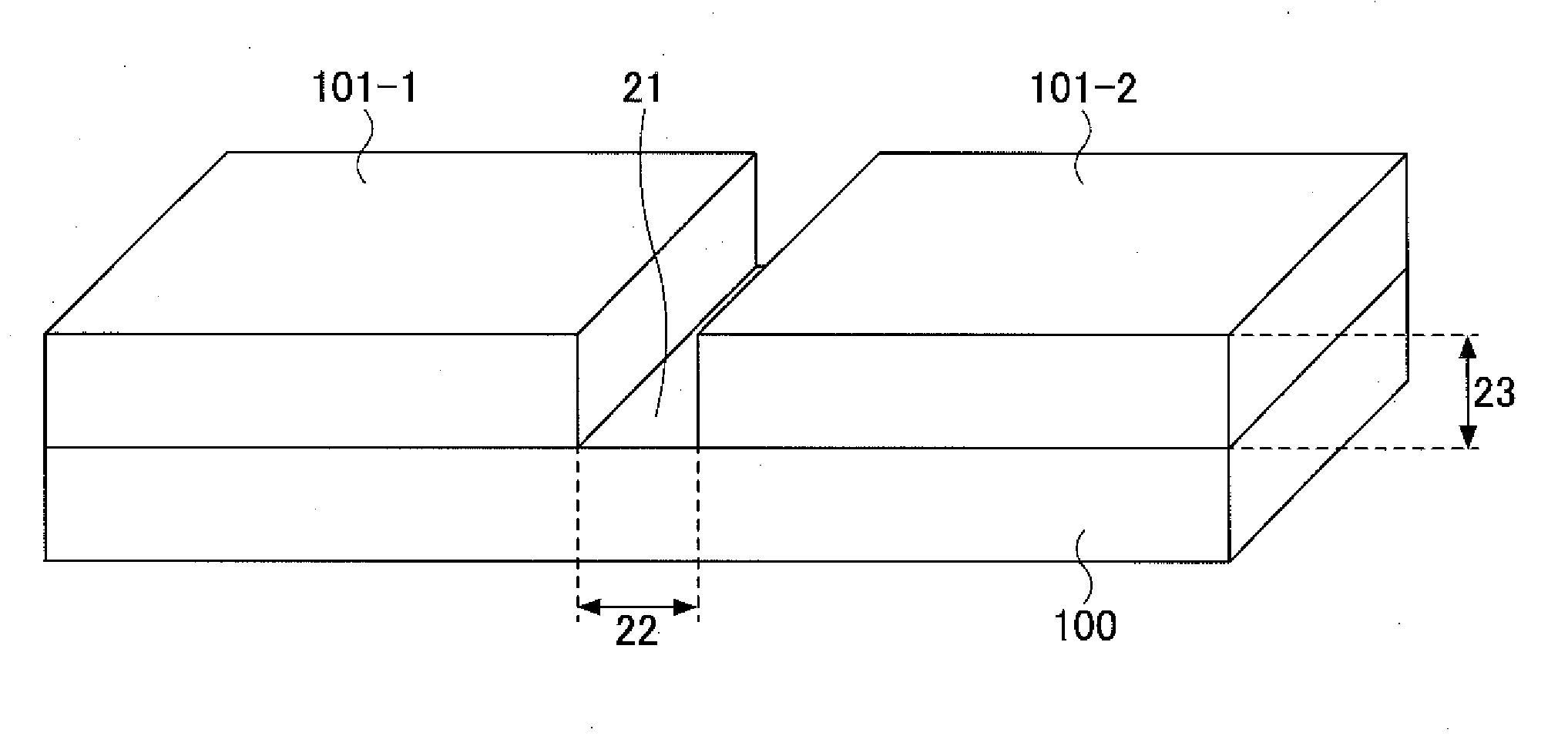
[0054]In samples No. 021 through No. 025 of the example embodiment Emb2, the shrinkage was 0.5 mm or less and small, and the workability was satisfactory (“o”), as illustrated in FIG. 2. In addition, the number of times the joint filler composition needs to be coated in order to make the joint part 11 flat and aligned to the surface of the adjacent base members 101-1 and 101-2 may be redu...


PUM

PropertyMeasurementUnit
grain diameteraaaaaaaaaa
mass ratioaaaaaaaaaa

Abstract

A joint filler composition may include 100 parts by mass of a base material, 1 to 20 parts by mass of inorganic hollow particles, and 3 to 20 parts by mass of a mineral having a chain structure or a layer structure.

Description

CROSS-REFERENCE TO RELATED APPLICATIONS[0001]This application is based upon and claims the benefit of priority of the prior Japanese Patent Applications No. 2011-104523 filed on May 9, 2011 and No. 2012-072169 filed on Mar. 27, 2012, the entire contents of which are incorporated herein by reference.BACKGROUND OF THE INVENTION[0002]1. Field of the Invention[0003]The present invention generally relates to joint filler compositions, and more particularly to a joint filler composition that fills a joint part between adjacent base members (or furrings) in order to make a height of the joint part approximately the same as that of a surface of the base members, when performing an interior finishing work on an inner wall or a ceiling of a building, for example.[0004]A joint filler composition may sometimes be referred to as a joint filling material, a joint sealing material, or a joint sealer.[0005]2. Description of the Related Art[0006]When performing the interior finishing work of the bui...

Claims


Application Information

Patent Timeline
Patent Type & Authority Applications(United States)
IPC IPC(8): C09D101/28C09D1/00C09D7/61
CPCC09D1/12C09D5/34C08K7/28C09D7/1291C09D7/1216C09D7/61C09D7/70
Inventor GOTO, TSUYOSHI
Owner YOSHINO GYPSUM CO LTD
Why Eureka
Try Eureka