Method and computing module for determining pitch angle adjustment signals of a wind turbine based on the maximum rotational speed

Active Publication Date: 2012-11-08
SIEMENS GAMESA RENEWABLE ENERGY AS
View PDF6 Cites 10 Cited by
  • Summary
  • Abstract
  • Description
  • Claims
  • Application Information

AI Technical Summary

Benefits of technology

[0014]In particular, taking into account the maximal speed signal of the rotation shaft for deriving the pitch angle adjustment signal (based on which the pitch angle will be adjusted) may improve, in particular increase, a power output of the wind turbine, and may reduce structural loads and / or acoustic noise. In particular, in order to capture the largest possible amount of energy from the wind, it may be important that the pitch angle reference and the power (or torque) reference are adapted to the current operational conditions. In particular, the inventors found that the optimal pitch setting may be strongly impacted by the maximum rotational speed for the particular operation mode. Thereby, exploiting this finding when setting the pitch reference to ensure optimal turbine operation may improve the power production.
[0042]According to an embodiment, when the second desired rotational speed is desired as the rotational speed of the rotation shaft, the adjusting the pitch angle to the second pitch angle results in a higher power output of the wind turbine than adjusting the pitch angle to the first pitch angle. Thereby, the power output of the wind turbine may be increased.

Problems solved by technology

It has been observed that adjusting a pitch angle of a rotor blade in particular in situations, where the wind turbine is operated below the rated power may be difficult.

Method used


Image

  • Method and computing module for determining pitch angle adjustment signals of a wind turbine based on the maximum rotational speed
  • Method and computing module for determining pitch angle adjustment signals of a wind turbine based on the maximum rotational speed
  • Method and computing module for determining pitch angle adjustment signals of a wind turbine based on the maximum rotational speed

Examples


Embodiment Construction

[0056]The illustration in the drawings is in schematic form. It is noted that in different figures, similar or identical elements are provided with the same reference signs or with reference signs, which are different from the corresponding reference signs only within the first digit.

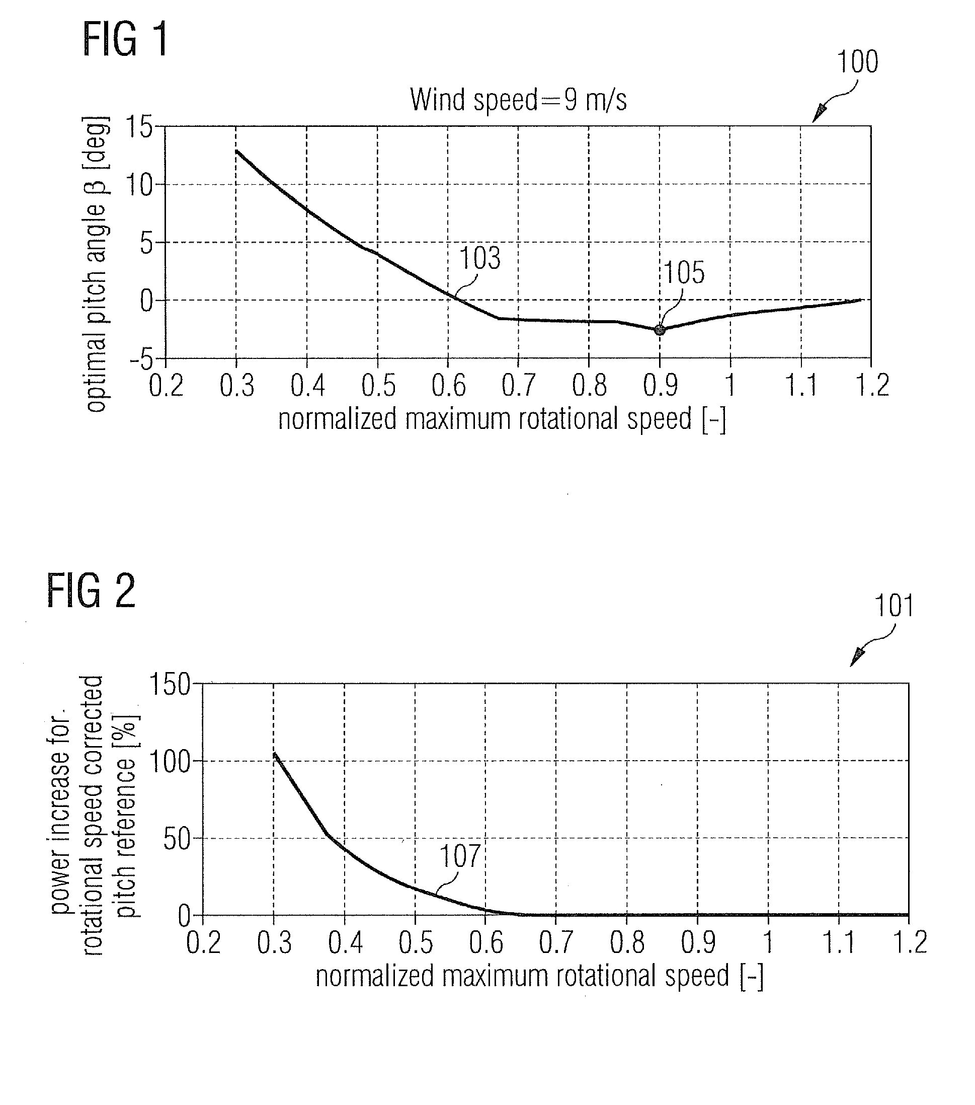
[0057]FIG. 1 illustrates a graph 100 showing on an ordinate the optimal pitch angle β and on an abscissa a normalized maximal rotational speed (as a ratio with respect to a design maximum rotational speed), wherein a curve 103 indicates the optimal pitch angle β in dependence of the normalized maximum rotational speed.

[0058]A point 105 at coordinates (1, −2°) may correspond to a situation, where the wind turbine is operated at the design rotational speed of the rotation shaft. According to regulations or a demand by a wind farm controller the maximum rotational speed may be set to be above or to be below the maximum design rotational speed.

[0059]The graph 100 illustrated in FIG. 1 relates to an external...


PUM


Abstract

A method and corresponding arrangement are provided for determining pitch angle adjustment signals for adjusting a pitch angle of a rotor blade connected to a rotation shaft of a wind turbine. The method includes obtaining a first maximal speed signal indicative of a first desired maximal rotational speed of the rotation shaft. The method also includes deriving a first pitch angle adjustment signal based on the first maximal speed signal. The method further includes obtaining a second maximal speed signal indicative of a second desired maximal rotational speed of the rotation shaft different from the first desired maximal rotational speed of the rotation shaft. Further, the method includes deriving a second pitch angle adjustment signal based on the second maximal speed signal. The second pitch angle adjustment signal is different from the first pitch angle adjustment signal.

Description

CROSS REFERENCE TO RELATED APPLICATIONS[0001]This application claims priority of European Patent Office application No. 11164590.9 EP filed May 3, 2011. All of the applications are incorporated by reference herein in their entirety.FIELD OF INVENTION[0002]The present invention relates to a method and a computing module for determining pitch angle adjustment signals for adjusting a pitch angle of a rotor blade connected to a rotation shaft of a wind turbine and further the present invention relates to a method and an arrangement for adjusting a pitch angle of a rotor blade or pitch angles of rotor blades of a wind turbine.BACKGROUND OF INVENTION[0003]A wind turbine may comprise a wind turbine tower, a nacelle mounted on top of the wind turbine tower, a rotation shaft rotatably supported within the nacelle, wherein the rotation shaft has one or more rotor blade connected to it. Impacting wind may transfer kinetic energy to the rotor blades which cause the rotation shaft to rotate. The...

Claims


Application Information

Patent Timeline
IPC IPC(8): F03D7/04F03D11/00
CPCF03D7/0224F03D7/043Y02E10/723F05B2270/335Y02E10/721F05B2270/32Y02E10/72
Inventor ESBENSEN, THOMASHOEGH, GUSTAV
Owner SIEMENS GAMESA RENEWABLE ENERGY AS
Why Eureka
Try Eureka