Medical delivery system and method for delivery of a medically useful payload

a technology of medically useful payload and delivery system, which is applied in the field of medical delivery system for delivering medically useful payload, can solve the problems of significant procedural delay and patient risk, difficulty in delivering wire wrapping, and difficult passage of vein segments, and achieve the effect of facilitating the rotation of payload

Inactive Publication Date: 2012-10-18
BURGERMEISTER ROBERT +6
View PDF3 Cites 0 Cited by
  • Summary
  • Abstract
  • Description
  • Claims
  • Application Information

AI Technical Summary

Benefits of technology

[0009]The present invention is directed to a system and method for the delivery of a medically useful payload to a target site within a patient's body. By way of example, the system may be a flexible catheter, and the medically useful payload may be a stent or atherectomy device. In these instances, the medically useful payload is delivered to a site of disease within a blood vessel of a patient. In yet other examples the medically useful payload may be a camera, a light, or both, which can be carried to a site where observation is warranted for purposes of making a medical diagnosis. In one aspect of the present invention, an orienting region exhibiting a curved shape is located at a distal end of the delivery device. The curved shape facilitates rotation of the payload into a desired position during delivery according to its preferential orientation. That is, the orienting distal region is curved or bent in a preferred direction that causes the device to rotate in accordance with the shape of the vessel or guidewire (if possessing a curved segment) on which the delivery device may be tracked in order to achieve desired orientation of the payload.
[0011]In another aspect of the present invention, the orienting member having a curved shape is distally located on the delivery device and is coupled thereto to allow a degree of torsional movement of the orienting member, relative to other parts of the device. That is, the orienting member is attached to the delivery device in a manner that allows the orienting member to rotate as necessary to orient the member and conform the distal end of the device, where the member is located, to the shape of the vasculature, in order to deploy or carry the payload so the payload can be properly oriented.
[0014]The curved shape imparted to the orienting member of the present invention facilitates orientation of the device as it travels through (1) curves or bifurcations in the vessel, (2) curves or bends in the guidewire, or (3) other eccentricities located within the vessel that create a curved path. So long as the orienting member possesses a sufficient degree of freedom to rotate, it will assume the path of least resistance in the course of its travels, and thereby rotate / orient itself to conform to the curve in the vessel in a unique, repeatable and predictable manner. Thus, by linking or associating a payload with the orienting member in a known relative position, orientation of the payload can be attained as a result of the rotational action exhibited by the orienting member.
[0015]Aside from being adapted to pass relatively easily through bends and curves in the vasculature, the self-orienting member can be used in a number of beneficial ways. Stents deployed at the site of or in the vicinity of a bifurcation may have asymmetrical design features intended to conform to the bifurcation, and in particular, the side branch ostium. Such stents must be deployed in the proper orientation, a result that can be obtained by coupling such stents to the orienting member, and then allowing the member to orient itself in the vessel. Likewise, a camera or other diagnostic tool, such as an ultrasound transducer (IVUS), pressure transducer, infrared sensor, endoscope lens coupled to the orienting member could be properly oriented as a result of orienting member orientation. Furthermore, the self-orienting nature is useful where the curve, so to speak, is imparted by the guidewire that passes through the catheter. For instance, the orienting member may travel over a guide wire passed into a bifurcation side branch, allowing a stent to be deployed, in its proper orientation, in the side branch. In yet another example, a guidewire having a pre-bent or curved section can be used to effect orientation of the orienting member in situations where vessel characteristics are not of an orientation-producing nature. In other words, by positioning the bend in the guidewire at the desired location, the orienting member will orient itself as it traverses the bend. This arrangement is advantageous where it is desirable to achieve orientation in a relatively straight vessel segment. In any event, with these arrangements, rotation of the orienting member for positioning of payload, whether for deployment or other medically useful purpose is facilitated. Further, it should be understood that with the orienting member of the present invention, it is not just the payload that is properly oriented. For example, in the case of a bifurcated vessel, the side branch guidewire exit port can be oriented to face the ostium of the side branch vessel. In other words, as the orienting member rotates, the side branch guidewire exit port aligns according to the orienting member orientation, with the side branch guidewire element facing the side branch ostium. This arrangement makes it possible for the orienting member to properly orient to the side branch anatomy when the device is seated at the carina of the bifurcation. This arrangement also makes it easier for the side branch guide wire to be advanced out of the delivery catheter and into the side branch.

Problems solved by technology

The vessel may have segments that are difficult to traverse.
First, by requiring delivery of the medical device to the location of the bifurcation over two wires (for substantially the entire delivery), the chance of wire wrapping is greatly increased.
This prevents complete delivery of the device and can result in the clinician having to withdraw a wire and rewire the vessels, causing significant procedural delay and patient risk.
Second, reliance on two wires for device orientation is typically insufficient to guarantee full and proper alignment of the entire medical device with the side branch ostium (particularly the portion of the device proximal to the carina (or apex) of the bifurcation).
Even when both branches of the bifurcation are wired and the medical device is seated on the carina, the wires are typically not able to exert enough rotational influence on the device to align the whole length of the payload.
In any event, carrying the payload through a vessel curvature, a bifurcation, or otherwise deploying the payload at such locations can present challenges in terms of traversing or accessing the site.
Furthermore, where the payload needs to be in a specific orientation (such as for maximizing the therapeutic effect or diagnostic purpose of the payload), achieving the desired orientation in such curvature or bifurcation presents yet another challenge to the person of skill in the art.

Method used


Image

  • Medical delivery system and method for delivery of a medically useful payload
  • Medical delivery system and method for delivery of a medically useful payload
  • Medical delivery system and method for delivery of a medically useful payload

Examples


Embodiment Construction

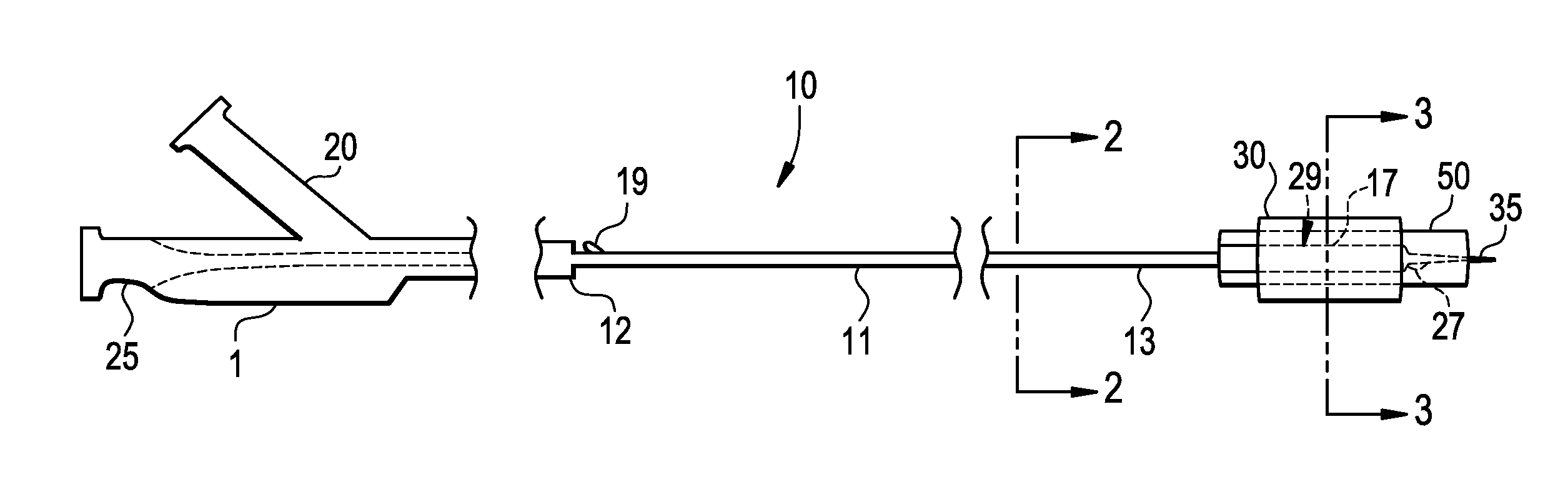
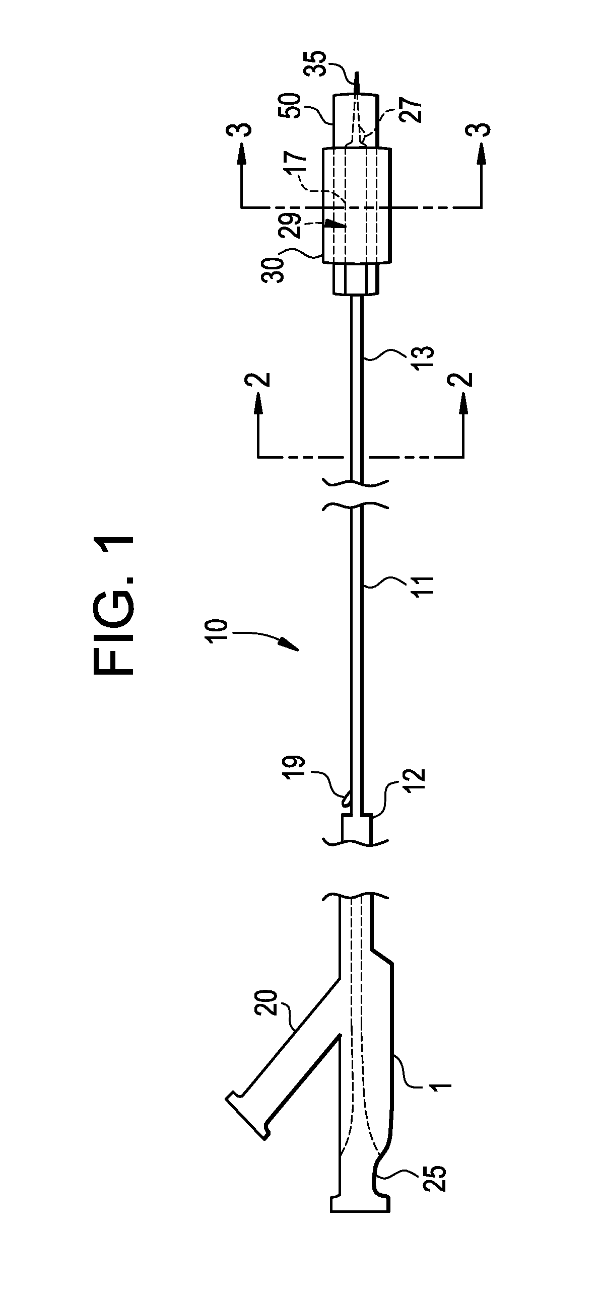
[0046]This invention describes a novel method and construction for designing the distal portion of a medical device delivery system. The delivery system can track the medical device towards a target location on a single wire, and pre-orient the payload of the delivery system relative to the target location. This design facilitates rotation of a payload into position for use. To accomplish this rotation, a curved shape is induced on the orienting member of the delivery system prior to advancement of the device to the target location. As an example in this embodiment, the curved shape should be chosen such that the curvature of the device is approximately matched to curvature in the vicinity of the target location. As the device rotates, the curve of the device aligns with the curve of the vessel, orienting the payload into the desired position.

[0047]In one particular embodiment, this invention describes a novel method and construction for designing the distal portion of a medical dev...


PUM


Abstract

The present disclosure concerns a delivery system for delivering a medically useful payload through the vasculature to a site of interest in the patient's body. The medically useful payload may be a therapeutic device, such as a stent, and it may be a diagnostic tool, such as an imaging device. Owing to its structural attributes, the presently-inventive delivery system is well suited for carrying medical payload to and through vessel curvature and to branched regions (i.e., bifurcations) in same. Also, the device is well-suited to traveling through a vessel over a guiding element, such as a guidewire, which itself exhibits curvature.

Description

CROSS REFERENCE TO RELATED APPLICATION[0001]This application reclaims priority under 35 U.S.C. §119 (e) to U.S. provisional patent application No. 60 / 757,123, filed Jan. 6, 2006.FIELD OF THE INVENTION[0002]The present disclosure concerns a delivery system for delivering a medically useful payload through a channel in the patient's body, such as the vasculature or a lumen, to a site of interest. The medically useful payload may be a therapeutic device, such as a stent, or it may be a diagnostic tool, such as a camera. Owing to its structural or shape attributes, the presently-inventive delivery system is well suited for carrying medical payloads to and through vessel curvature and to branched regions (e.g., bifurcations) in same. Also, the device is well-suited to traveling through a vessel over a guiding element, such as a guidewire, which itself exhibits curvature.BACKGROUND OF THE INVENTION[0003]Diseases of the vasculature, such as stenoses, strictures or aneurysms in blood vessel...

Claims


Application Information

Patent Timeline
Patent Type & Authority Applications(United States)
IPC IPC(8): A61F2/84
CPCA61F2/95A61M25/01A61M25/0105A61M25/0158A61M25/0152A61M25/0155A61M25/0147
Inventor BURGERMEISTER, ROBERTKREVER, MATHEW ERICFERRARA, PAULDI CAPRIO, FERNANDOSMEISER, RICCI DAYLEBEYREIS, RANDALL JAMESHATCHER, BRADY JAMES
Owner BURGERMEISTER ROBERT
Why Eureka
Try Eureka