
Ball Bearing and Corresponding Bump Stop

a technology of ball bearings and bump stops, which is applied in the direction of ball bearings, suspensions, and resilient suspensions, etc., can solve the problems of high unequal distribution of constraints between balls, sliding generating rapid wear, and malfunctioning bearings

Inactive Publication Date: 2012-10-04
TORRINGTON COMPANY
View PDF7 Cites 4 Cited by
  • Summary
  • Abstract
  • Description
  • Claims
  • Application Information

AI Technical Summary

Benefits of technology

"The invention proposes a bearing with improved rigidity and resistance to radial forces. This is achieved by designing a bearing with a lower and upper raceway that can better withstand radial forces. The bearing is particularly useful in a bump stop application where it is subjected to high levels of force. The geometry of the lower and upper raceways is designed to provide a better angle of obliquity, allowing for better centering of the bearing. The bearing is also designed to be more compact and sealing is improved. The invention also includes a thrust bearing that can be used in conjunction with a lower supporting means to transmit forces from a suspension spring. The angle of obliquity is open towards the lower supporting means for better centering. The bearing is also designed to be compatible with plastic material for the supporting means. Overall, the invention provides a bearing with improved rigidity and resistance to radial forces, making it better suited for high-load applications."

Problems solved by technology

Yet the solicitations of such a stop are multidirectional and dissymmetrical, which results in constraints that are highly unequally distributed between the balls.
The potential malfunction of the bearing can also be manifested via a stick-slip motion of the balls with sudden losses of adherence interrupting the bearing of certain balls on the raceways and causing sliding generating rapid wear.
Moreover, the plastic parts that comprise the spring support and the cover, if they are undersized, can also undergo deformations and come into contact with each other, which accentuates the malfunction of the stop.

Method used


Image

  • Ball Bearing and Corresponding Bump Stop
  • Ball Bearing and Corresponding Bump Stop
  • Ball Bearing and Corresponding Bump Stop

Examples


Embodiment Construction

)

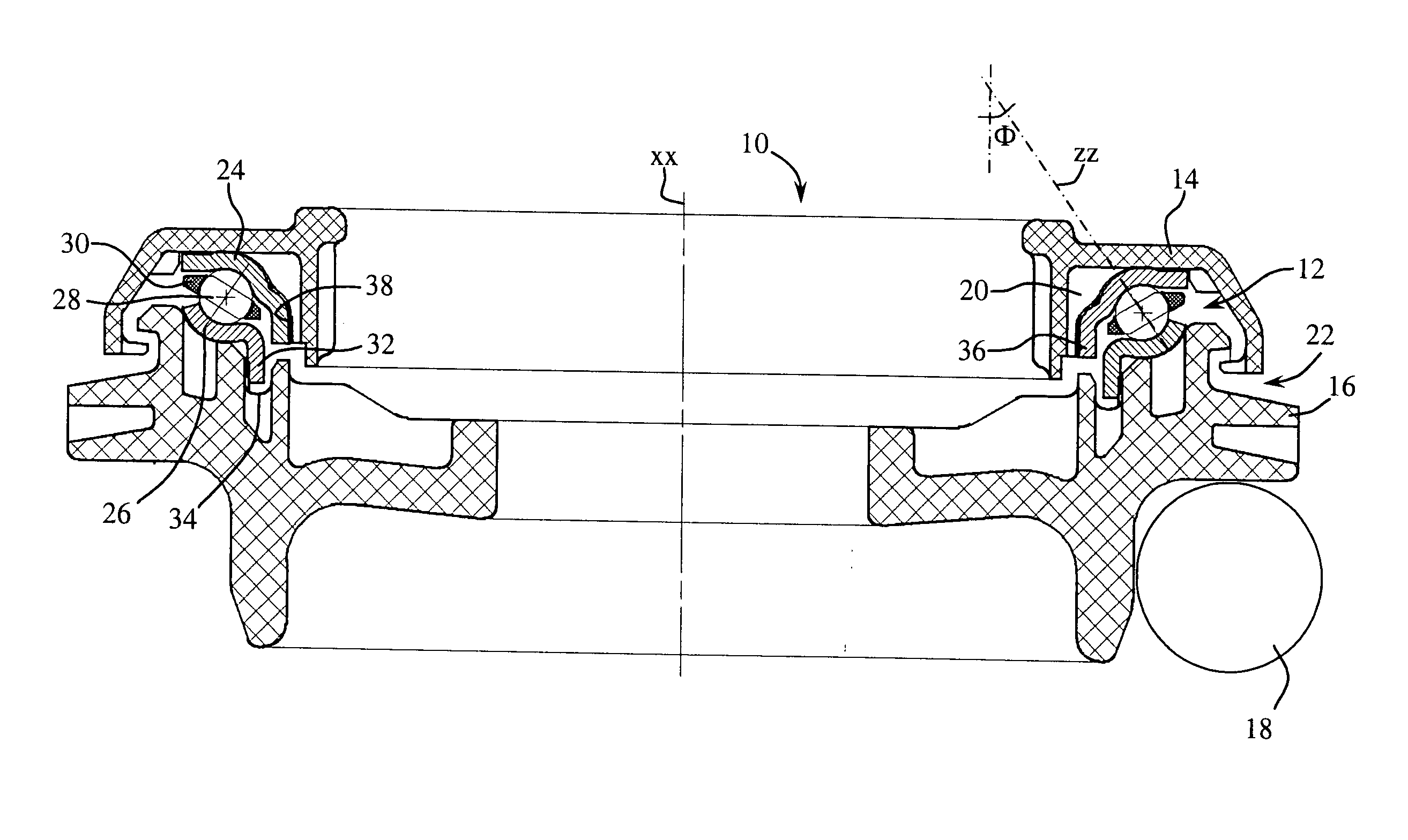
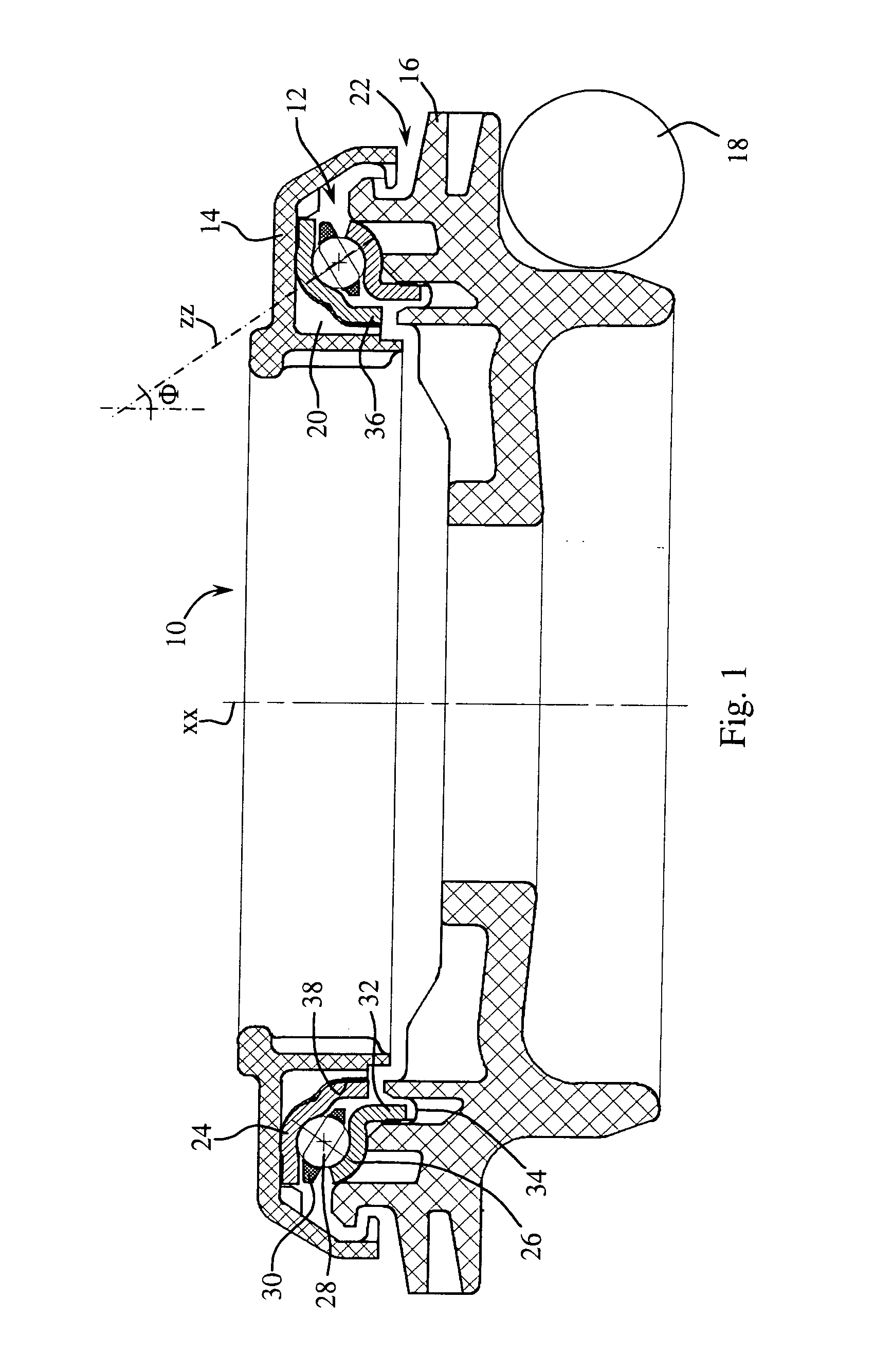
[0029]FIG. 1 shows a bump stop 10 comprising a ball bearing inserted between a cover 14 constituting an interface with the body of the vehicle and a lower supporting part 16 intended to come to rest, directly or with interposition of a rubber dampening ring, on the upper spire of a helical suspension spring 18. The cover 14 and the lower supporting part 16 are made from plastic materials. Their forms define an annular housing 20 for the bearing 12, which opens onto the exterior via a baffle 22.

[0030]The bearing 12 is comprised of an upper washer 24 fixed to the cover 14, of a lower washer 26 pressing against the lower supporting part 16, the washers defining between them an annular volume wherein are housed balls 28 retained where applicable by a cage 30.

[0031]Each of the washers 24, 26 is comprised of sheet metal, formed more preferably by stamping.

[0032]On the lower washer 26 is defined a lower raceway, which in a known manner is a surface of revolution of which the generating li...


PUM


Abstract

A bearing for an angularly contacting bump stop, the washers of which consist of stamped sheet metal and have a surrounding geometry. The geometry of the bearing is such that, in every cutaway containing the geometrical axis of rotation of the bearing, the lower raceway forms a lower circle arc which defines a lower axial curvature center, the upper raceway forms an upper circle arc which defines an upper axial curvature center, the upper and lower curvature centers being located on an angular geometrical axis that forms with the geometrical axis of rotation an angle of obliquity of a value between 5° and 65°. Specifically, the lower circle arc has two ends defining an opening angle of a value greater than or equal to 80° and a tangent located in a lower plane perpendicular to the axis of rotation at a lower tangent point defining with the end of the nearest lower circle arc a portion of the lower circle arc having an opening angle greater than or equal to 10°.

Description

BACKGROUND[0001]1. Technical Field of the Invention[0002]The invention relates to a vehicle bump stop, provided with a ball bearing.[0003]2. Prior Art[0004]The use of a bearing with washers made from stamped sheet metal in bump stops is presented for example by document FR2918138. In such a stop, one of the washers materialising the raceways, referred to as the lower washer, is pressing against a plastic support constituting an interface with a helical suspension spring of the wheel, the other washer, referred to as the upper washer, pressing under a cover fixed to the body of the vehicle. The raceways have as a section a profile in the form of a circle arc of which the opening angle is 60°. The raceway of the lower washer is open radially towards the interior and does not comprise any edge that can radially limit the movement of the balls towards the interior. This results from the fact that the circle arc of the raceway of the lower washer is not at any point tangent to a plane pe...

Claims


Application Information

Patent Timeline
Patent Type & Authority Applications(United States)
IPC IPC(8): F16C19/04
CPCB60G15/068B60G2204/128F16C33/588F16C19/10F16C2326/05B60G2204/418B60G15/06F16C33/58
Inventor BRISSON, SEBASTIENCHAMOUSSET, ANTONY
Owner TORRINGTON COMPANY
Learn More