
Solid State Bidirectional Light Sheet Having Vertical Orientation

a light sheet and solid state technology, applied in the direction of lighting and heating equipment, instruments, lighting support devices, etc., can solve the problems of adding considerable cost and complexity to the light sheet, and achieve the effect of broad illumination

Active Publication Date: 2012-10-04
QUARKSTAR
View PDF2 Cites 43 Cited by
  • Summary
  • Abstract
  • Description
  • Claims
  • Application Information

AI Technical Summary

Benefits of technology

[0009]The light sheets used in embodiments of the present invention employ conductors on the substrates that electrically contact the LED electrodes without using wires. The conductors may connect any number of LEDs in series and are ultimately connected to a power source. In another embodiment, wires may be used for the connections, adding considerable cost and complexity to the light sheet.
[0013]In an application of a bidirectional light sheet, the sheet (e.g., a strip) may be suspended from a ceiling so that it is orientated vertically (i.e., perpendicular to the ceiling and floor). Optics may be molded into the light emitting surfaces to angle the peak light intensity downward (e.g., at 55 degrees relative to vertical) to avoid glare and to merge the light of one fixture with light from adjacent fixtures. Other ways of directing the light may also be used, such as locating the LED chips in reflective cups or deep wells that emit a collimated beam of light at any selected angle. Portions of the light sheet, or another light sheet in the same fixture, may also be designed to direct light upward to reflect off the ceiling to achieve broad illumination. Any combinations of peak intensity angles may be achieved.

Problems solved by technology

In another embodiment, wires may be used for the connections, adding considerable cost and complexity to the light sheet.

Method used


Image

  • Solid State Bidirectional Light Sheet Having Vertical Orientation
  • Solid State Bidirectional Light Sheet Having Vertical Orientation
  • Solid State Bidirectional Light Sheet Having Vertical Orientation

Examples


Embodiment Construction

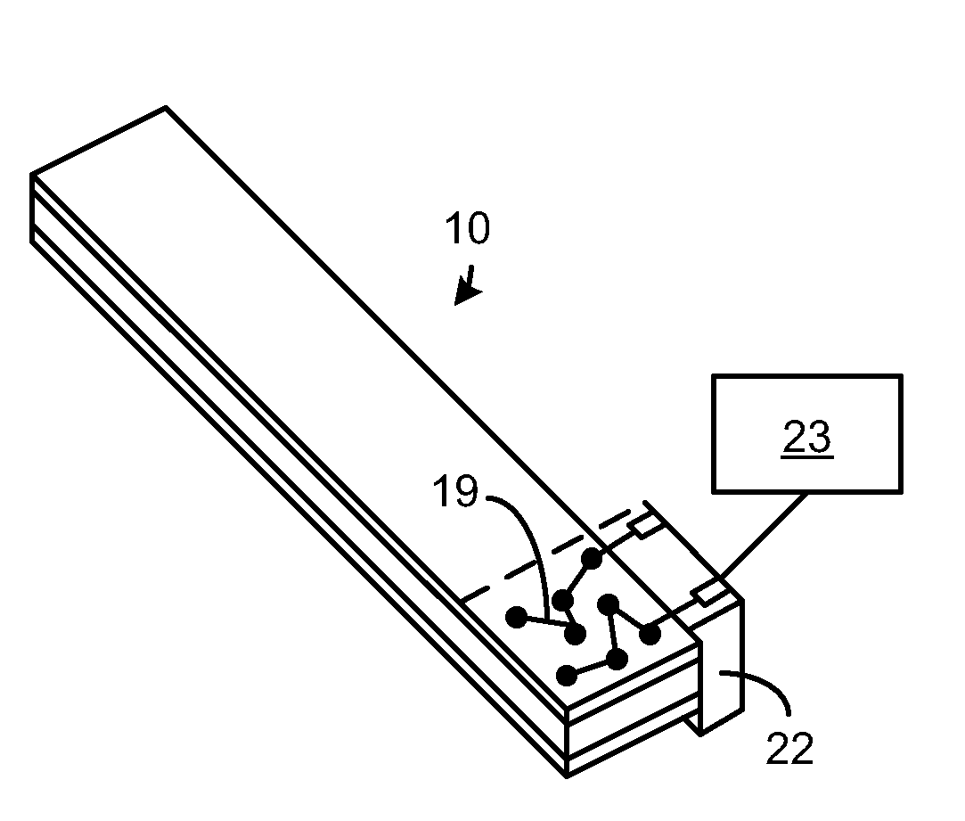
[0032]FIG. 1 is a perspective view of a portion of a light sheet 10, showing a simplified pseudo-random pattern of LED areas 12. The LED areas 12 may instead be in an ordered pattern. There may be 500 or more low power LEDs in the light sheet 10 to generate the approximately 3700 lumens (per the DOE CALiPER benchmark test) needed to replace a standard fluorescent fixture typically found in offices.

[0033]The pseudo-random pattern may repeat around the light sheet 10 (only the portion within the dashed outline is shown). A pseudo-random pattern is preferred over an ordered pattern since, if one or more LEDs fail or have a poor electrical connection, its absence will be significantly harder to notice.

[0034]In one embodiment, the light sheet 10 is generally formed of three main layers: a transparent bottom substrate 14 having an electrode and conductor pattern; an intermediate sheet 16 acting as a spacer and optional reflector; and a transparent top substrate 18 having an electrode and ...


PUM


Abstract

A solid state, bidirectional light sheet and method of fabricating the sheet are disclosed. In one embodiment, bare LED chips have top and bottom electrodes, where the bottom electrode is a large reflective electrode. An array of LEDs (e.g., 500 LEDs) is sandwiched between at least two transparent substrates having conductors bonded to the electrodes without wires. Various ways to connect the LEDs in series are described along with various embodiments. The light sheets are formed to emit light from opposite surfaces of the light sheet to create a bidirectional light sheet. The light sheet may be suspended from a ceiling to be perpendicular to the ceiling, or the angles of the light sheet may be adjusted. The suspended light sheet may form a cylinder for uniform illumination of the floor and ceiling. Lenses may be formed in the light sheet to emit light at any peak intensity angle to achieve any light emission pattern.

Description

FIELD OF INVENTION[0001]This invention relates to solid state illumination and, in particular, to a substantially flat bidirectional light sheet containing light emitting dies, such as light emitting diodes (LEDs), where the light sheet is orientated at a non-parallel angle, such as vertically, with respect to a ceiling.BACKGROUND[0002]High power LEDs are the conventional choice for general solid state lighting applications. Such high power white LEDs are extremely bright and can have luminous efficacies between 100 and 200 lumens / watt. The input power of a single high-power LED is typically greater than 0.5 watt and may be greater than 10 watts. Such LEDs generate considerable heat since they are only about 1 mm2 in area, so the required packaging is fairly complex and expensive. Although a bare high-power LED chip typically costs well under $1.00 (e.g., $0.10), the packaged LED typically costs around $1.50-$3.00. This makes a high output (e.g., 3000+lumens) solid state luminaire r...

Claims


Application Information

Patent Timeline
IPC IPC(8): F21V5/04F21V21/00
CPCF21S8/04F21S8/06H01L2924/0002F21V7/0016F21Y2101/02H01L25/0753H01L25/0756H05K1/189H05K2201/10106F21K9/50F21V5/02F21V5/04F21V7/00F21V21/14H01L2924/00F21V5/10F21Y2107/90F21Y2109/00F21Y2115/10F21K9/60F21Y2105/10F21S8/046F21S8/068F21V21/16F21V23/06
Inventor DAU, WILSONLERMAN, LOUISYORK, ALLAN BRENT
Owner QUARKSTAR
Learn More