
Efficient vehicle power systems

a technology of efficient vehicle power system and power supply, applied in the direction of electric propulsion mounting, propulsion by batteries/cells, jet propulsion mounting, etc., can solve the problems of increasing engine output power, reducing vehicle fuel economy, and low fuel efficiency of such engines, and achieve the effect of reducing siz

Active Publication Date: 2012-10-04
3B TECH II
View PDF9 Cites 12 Cited by
  • Summary
  • Abstract
  • Description
  • Claims
  • Application Information

AI Technical Summary

Benefits of technology

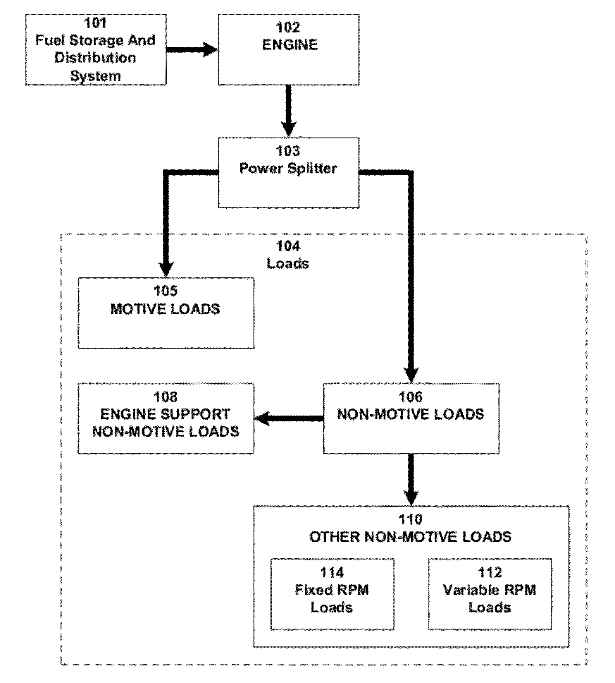
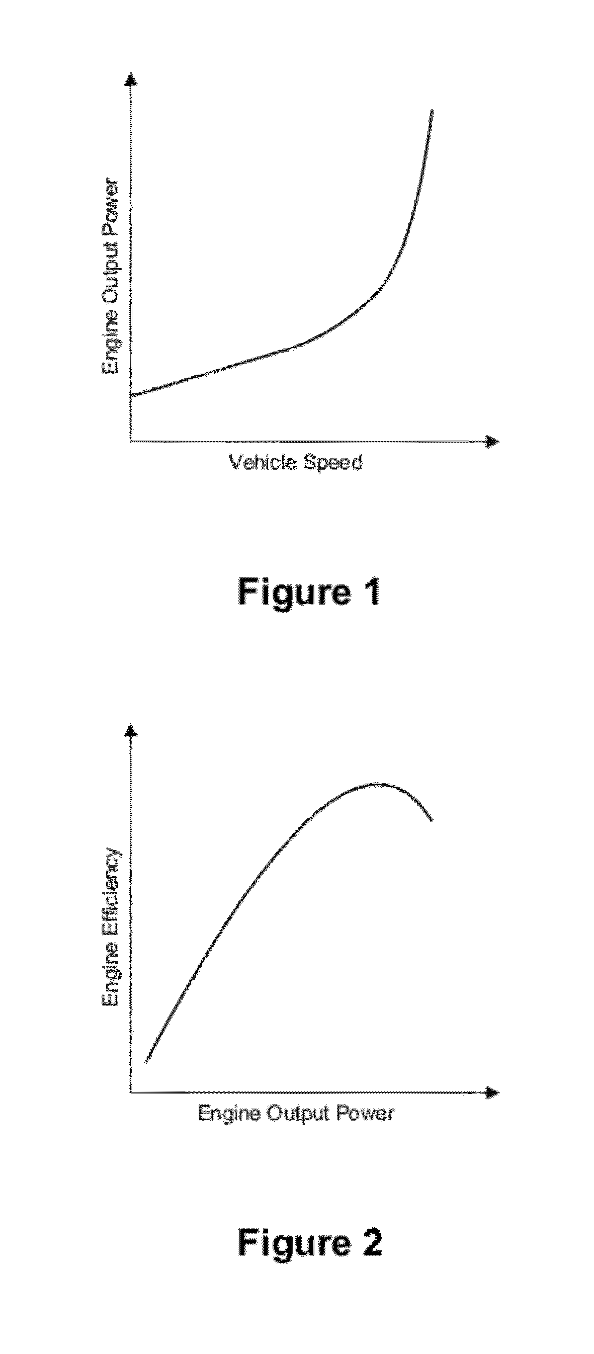
[0021]The explosion of non-motive auxiliary roads found in modern vehicles calls into question the very concept of whether MPG remains an accurate measure of fuel efficiency. These auxiliary loads have increased to a point where a significant amount of fuel is consumed providing power for these auxiliary loads 112. As illustrated in FIG. 5, activation of an auxiliary load such as the air conditioning compressor will both increase engine output power and reduce vehicle fuel economy. Additionally, as illustrated in FIGS. 6A & 68, off-peak engine loads are far below that of peak power output. Yet, a conventional power system utilizes an engine with sufficient potential to individually deliver peak power. The fuel efficiency of such an engine is low when that engine is providing power for off-peak engine loads. Stated in a slightly different fashion, conventional vehicle power systems, operated under off-peak conditions, will require only a small fraction of their maximum power output but at a very reduced efficiency.
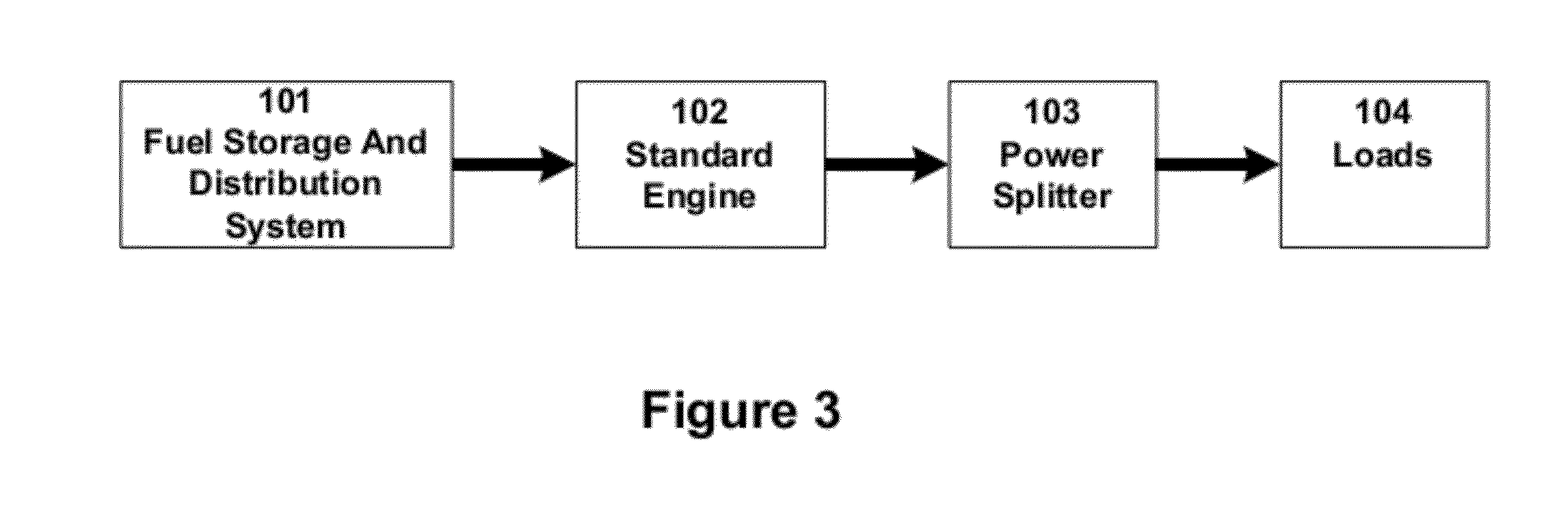
[0023]An efficient vehicle power system (EVPS) can be viewed as one which, under identical loading (operating and / or performance criteria), consumes significantly less fuel than a conventional power, system of high output power capability. Another characteristic of an EVPS is that larger reductions in fuel consumption coincide with the most frequently encountered loading conditions (typical or average loading). For example, based on the engine efficiency and fuel consumption characteristics described above, an EVPS could be configured such that under typical loading (operating and / or performance criteria), power was provided by a small engine (comparably sized to the typical load). This small engine should therefore have both high efficiency and low fuel consumption for typical vehicle loading). Output power from said small engine could be combined with other small engines to produce the required higher average power.
[0026]The present disclosure is an EVPS for converting potential energy stored within any of a wide variety of chemical molecules (fuel) into useful work wherein said conversion occurs over a wide, dynamic range of system operating loads, and where typical (average) system load power is substantially below the peak output power capability of said conversion system. Exemplary implementations of the present disclosure provide low cost realization of efficiency profiles that conform to the superior profile of FIG. 6B. The present disclosure describes power conversion for a wide variety of portable and mobile applications and addresses matching between power source characteristics and load conditions.
[0028]In some exemplary implementations, the present disclosure matches the different loads or combinations of loads to an appropriate array of engines thereby utilizing the fuel more efficiently.
[0031]In some exemplary implementations, vehicle fuel efficiency is improved by more closely matching the output power capability of one or more power array sources to individual load requirements at the point in time when the required load power is being delivered.

Problems solved by technology

As illustrated in FIG. 5, activation of an auxiliary load such as the air conditioning compressor will both increase engine output power and reduce vehicle fuel economy.
The fuel efficiency of such an engine is low when that engine is providing power for off-peak engine loads.
Stated in a slightly different fashion, conventional vehicle power systems, operated under off-peak conditions, will require only a small fraction of their maximum power output but at a very reduced efficiency.

Method used


Image

  • Efficient vehicle power systems
  • Efficient vehicle power systems
  • Efficient vehicle power systems

Examples


Embodiment Construction

[0063]The detailed description set forth below, or elsewhere herein, including any charts, tables, or figures, is intended as a description of presently-preferred embodiments of the invention and is not intended to represent the only forms in which the present invention may be constructed or utilized, nor is it intended to limit the scope of any claims based thereon.

[0064]In the following description various exemplary implementations, aspects and characteristics are discussed as directed toward vehicular and particularly automotive applications. The focus on automotive applications is not intended to be, nor should it act as, a limitation to the scope of this disclosure, marine, and air vehicles may also benefit from the disclosure. Automotive also includes automobiles and light duty trucks (terrestrial vehicles), which at present most frequently use single, gasoline burning, ICE power systems to provide power to produce vehicle motion and to operate all vehicle auxiliary and suppor...


PUM


Abstract

An improved gas-electric power delivery system is provided. The invention provides an array of internal combustion engine-powered electric generators and an array of electric drive motors wherein each electric drive motor connects to a common shaft. The common shaft of the electric drive motor array connects to a mechanical load of varying power demand. The electric drive motors draw power from a battery in response to demands on the motors by the varying power demands of the external load. The array of electric generators charges the battery and each such generator turns on and off, as needed, to maintain the battery charge in response to demands on the battery by the electric drive motor array. Each electric motor connected to a common shaft in the electric motor array also turns on and off, as needed, to meet the varying power demands of the external load.

Description

CROSS-REFERENCE TO RELATED APPLICATIONS[0001]This patent application is a continuation-in-part of U.S. Non-Provisional patent application Ser. No. 12 / 060,820 filed Apr. 1, 2008 for Efficient Vehicle Power Systems, which application is incorporated in its entirety herein by this reference.BACKGROUND OF THE INVENTION[0002]1. Technical Field[0003]This disclosure relates generally to motive power systems and more particularly to a method, system and process for improving efficiency by matching power to load requirements during motive vehicular use.[0004]2. Background[0005]For a typical moving vehicle at lower speed levels, rolling resistance is a predominant loss mechanism providing a nearly linear relationship between power increases and speed increases as shown in the typical power versus speed profile for a vehicle under an operating condition set forth in FIG. 1. At higher speed levels, air drag becomes a factor as well and those losses show a non-linear relationship. A well-accepte...

Claims


Application Information

Patent Timeline
Patent Type & Authority Applications(United States)
IPC IPC(8): H02P25/30B60L50/15
CPCB60K1/02B60K5/08B60K2025/022Y02T10/6217Y02T10/7077Y02T10/7005Y02T10/648B60L11/123B60L50/61Y02T10/62Y02T10/70Y02T10/64Y02T10/7072
Inventor WASHBURN, ROBERT D.MCCLANAHAN, ROBERT F.
Owner 3B TECH II
Learn More