
Temperature control apparatus for samples storage

a temperature control apparatus and sample technology, applied in lighting and heating apparatus, process and machine control, instruments, etc., can solve the problems of deviation in temperature between solutions in large-surface multi-wells containing samples and storage periods of manufactured samples

Inactive Publication Date: 2012-09-27
SAMSUNG TECHWIN CO LTD
View PDF11 Cites 13 Cited by
  • Summary
  • Abstract
  • Description
  • Claims
  • Application Information

AI Technical Summary

Benefits of technology

[0021]The temperature control unit may further comprise a heat sink contacting a side of the heat source portion.
[0022]The temperature control unit may further comprise a cooling fan disposed on a side of the heat source portion.
[0023]The temperature control unit may further comprise: a temperature sensor measuring a temperature of the well block; and a controller controlling the heat source portion to analyze the temperature of the well block that is measured by using the temperature sensor and to control the temperature of the well block to be uniform.
[0024]The temperature control apparatus may further comprise an adhesion member disposed between the heat transfer object and the heat source portion, wherein the adhesion member fills an aperture between the heat transfer object and the heat source portion, and the heat or the cold of the heat source portion is transferred to the heat transfer object via the adhesion member.
[0025]The temperature control apparatus may further comprise an adhesion member disposed between the well block and the heat transfer object, wherein the adhesion member fills an aperture between the heat transfer object and the well block, and the heat or the cold transferred from the heat source portion to the heat transfer object is transferred to the well block via the adhesion member.

Problems solved by technology

If there is deviation in temperatures of solutions in the wells of the container, results of data of samples that are experimented upon are unreliable, and storage periods of the manufactured samples may vary, which has become a main issue in the field.
In apparatuses for maintaining temperature according to the related art, a problem of deviation in temperatures between solutions in large-surface multi-wells containing samples occurs away from a heat source such as a heating / cooling device or a thermoelectric device.

Method used


Image

  • Temperature control apparatus for samples storage
  • Temperature control apparatus for samples storage
  • Temperature control apparatus for samples storage

Examples


Embodiment Construction

[0032]An inventive concept will now be described more fully with reference to the accompanying drawings, in which exemplary embodiments are shown. Expressions such as “at least one of,” when preceding a list of elements, modify the entire list of elements and do not modify the individual elements of the list.

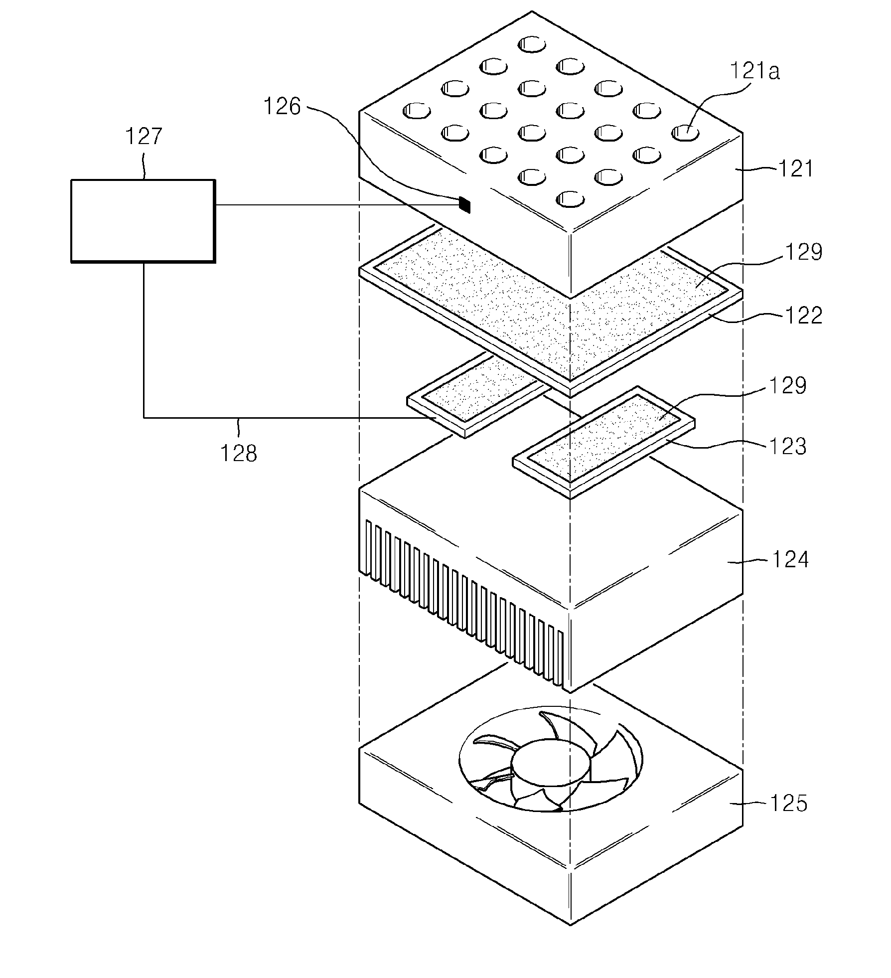
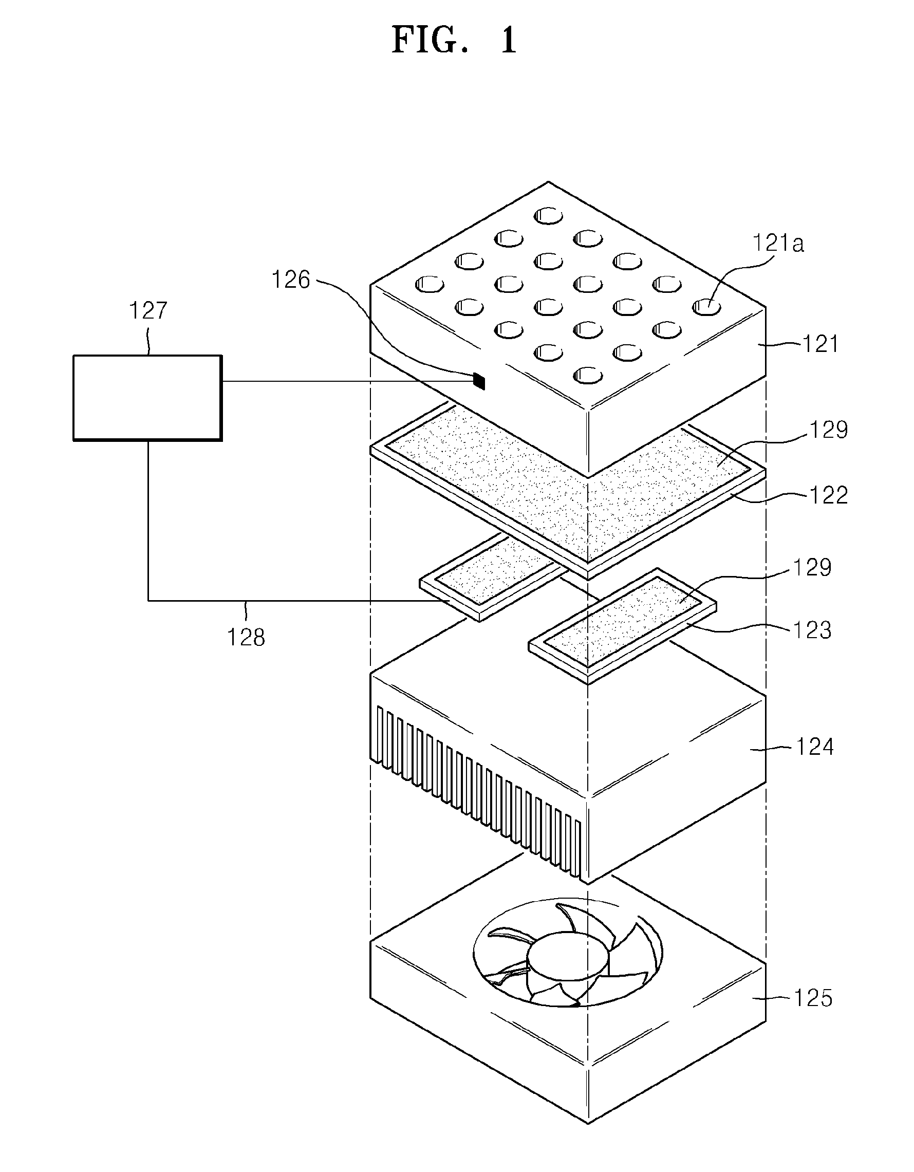
[0033]FIG. 1 is an exploded perspective view schematically illustrating a temperature control apparatus for sample storage, according to an exemplary embodiment.

[0034]Referring to FIG. 1, the temperature control apparatus may include a well block 121 and a temperature control unit.

[0035]The temperature control unit may include a heat transfer object 122, a heat source portion 123, a heat sink 124, a cooling fan 125, a temperature sensor 126, and a controller 127.

[0036]The well block 121 may include at least one accommodation groove 121a accommodating containers 210 (see FIG. 4) for containing samples. The accommodation grooves 121a are concavely formed toward an inner portion of...


PUM


Abstract

A temperature control apparatus for sample storage includes: a well block comprising at least one accommodation groove accommodating at least one container for containing at least one sample therein, respectively; and a temperature control unit controlling a respective temperature of the at least one sample to be uniform, wherein the temperature control unit includes: a heat source portion generating heat or cold; and a heat transfer object transferring the heat or the cold of the heat source portion to the well block.

Description

CROSS-REFERENCE TO RELATED PATENT APPLICATION[0001]This application claims priority from Korean Patent Application No. 10-2011-0025392, filed on Mar. 22, 2011, in the Korean Intellectual Property Office, the disclosure of which is incorporated herein in its entirety by reference.BACKGROUND[0002]1. Field[0003]Apparatuses consistent with exemplary embodiments relate to temperature control for sample storage.[0004]2. Description of the Related Art[0005]Bio equipment is a scientific instrument used in researching phenomena of life, and specifically, is used to study and understand biological phenomena of stages of molecules, cells, and individuals using physical or chemical principles.[0006]More specifically, bio equipment is used to conduct researches in bio technology such as gene modification techniques (e.g., recombination deoxyribonucleic acid (DNA) technique, gene cure, cloning, and antisense), biological sample analysis techniques using absorption, phosphorescence, and Raman spec...

Claims


Application Information

Patent Timeline
Patent Type & Authority Applications(United States)
IPC IPC(8): G05D23/00F25B21/02
CPCB01L7/00B01L7/52B01L2300/0829B01L2300/1822F25B2700/2107G05D23/1919F25B21/04F25B23/006B01L2300/1844F28D15/0275F28D2021/0077C12M1/18C12M1/38
Inventor HONG, JIN-KWANGLEE, SUNG-HUN
Owner SAMSUNG TECHWIN CO LTD
Learn More