
Heating body and vacuum sintering furnace capable of achieving multi-region temperature control

A technology of vacuum sintering furnace and heating body, applied in lighting and heating equipment, furnace, charge and other directions, can solve the problems of large temperature deviation, large deviation of product size and performance, poor temperature control and adjustability of equipment, etc., to achieve the temperature difference value The effect of shrinking, improving the full furnace yield, and increasing the heating rate

Active Publication Date: 2018-08-28
NINGBO HIPER VACUUM TECH CO LTD
View PDF6 Cites 5 Cited by
  • Summary
  • Abstract
  • Description
  • Claims
  • Application Information

AI Technical Summary

Problems solved by technology

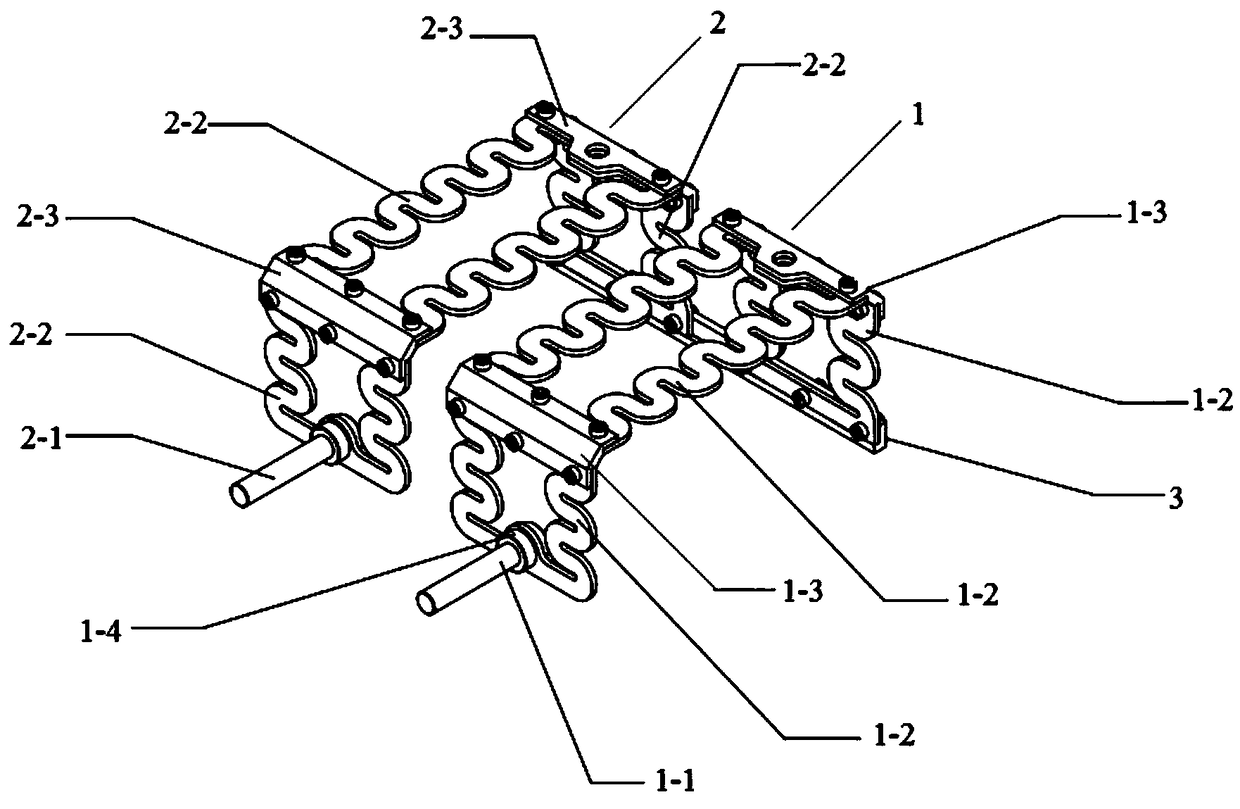
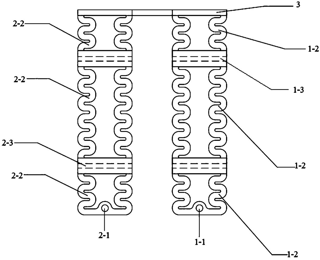
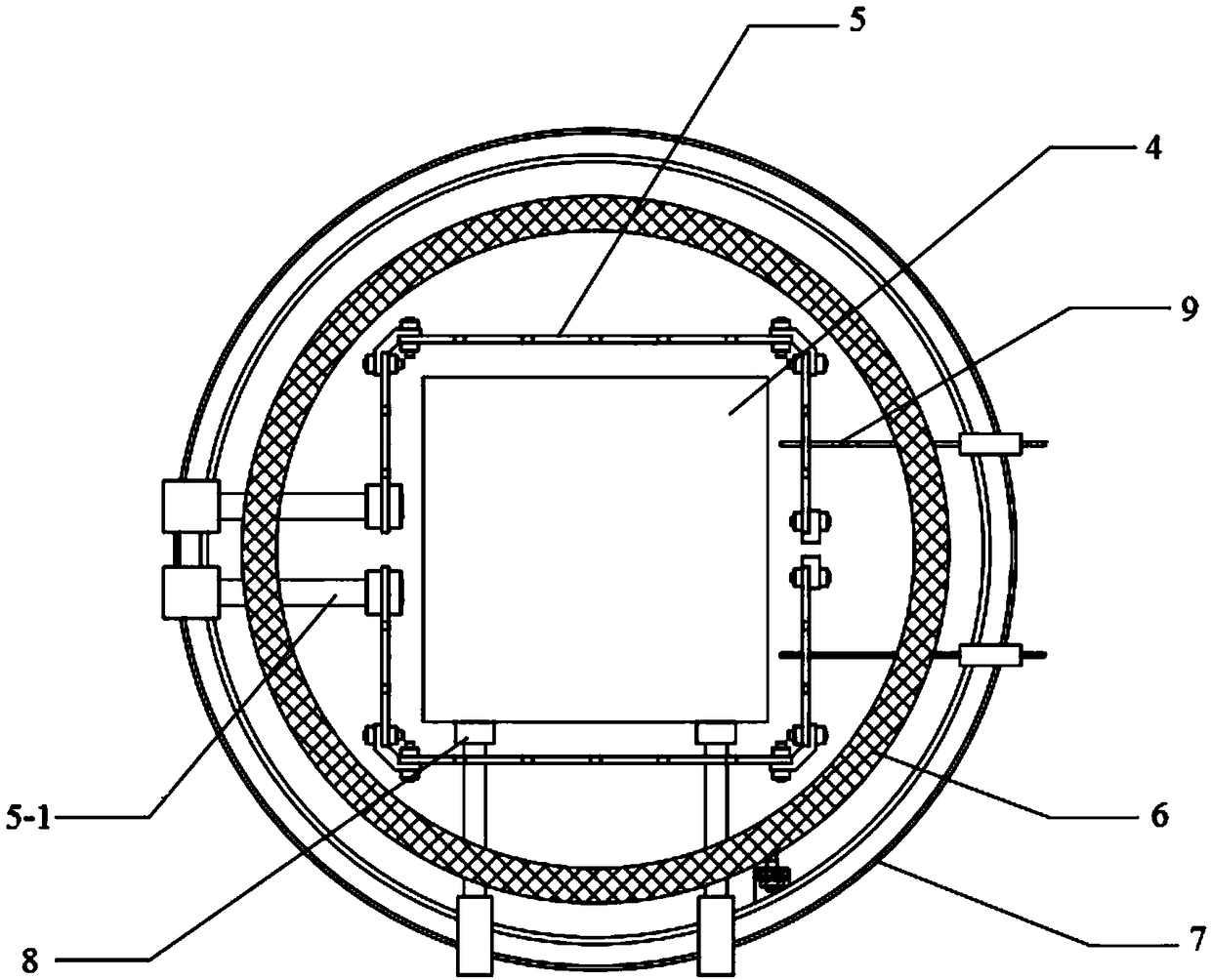
[0004] The purpose of the present invention is to provide a heating body and a vacuum sintering furnace that realizes multi-zone temperature control, so as to solve the problem that the existing integrated heating device has a large temperature deviation between up and down, front and back, resulting in large product size and performance deviations, and equipment The problem of poor temperature control and adjustability, thereby reducing the manufacturing cost and product production cost of the vacuum sintering furnace

Method used


Image

  • Heating body and vacuum sintering furnace capable of achieving multi-region temperature control
  • Heating body and vacuum sintering furnace capable of achieving multi-region temperature control
  • Heating body and vacuum sintering furnace capable of achieving multi-region temperature control

Examples


specific Embodiment approach

[0044] A specific implementation of the present invention is as follows:

[0045] The furnace body will be debugged and tested before shipment, and the temperature distribution is a necessary test.

[0046] For example, when the set temperature in the furnace is 800℃, the temperature is detected at 6 points in the furnace through the sensor, such as Image 6 As shown, Image 6 It is a schematic diagram of the distribution of temperature detection points in the furnace according to the specific embodiment of the present invention. The black dots represent the detection points, and the temperature measured at each detection point is as follows:

[0047] Point 1 is 800°C, point 2 is 810°C, point 3 is 795°C, point 4 is 800°C, point 5 is 805°C, and point 6 is 790°C.

[0048] At this time, point 1 is 800°C and point 6 is 790°C.

[0049] At this time, if the upper and lower two-zone temperature control design is adopted, that is, two heating bodies are used for heating. Since point 1 and poi...


PUM


Abstract

The invention discloses a heating body and a vacuum sintering furnace capable of achieving multi-region temperature control. The vacuum sintering furnace comprises an airtight box, a heating device and a heat-insulation cylinder. The heating device comprises a plurality of heating body sets which are evenly distributed outside the airtight box. Each heating body set comprises two heating bodies which are of the same structure and surround the side face of the airtight box. Each heating body comprises a first heating structure and a second heating structure, wherein the head end of the first heating structure and the head end of the second heating structure are connected with the output end of a single-phase transformer, the tail end of the first heating structure and the tail end of the second heating structure are connected with a long connecting piece, and the single-phase transformer, the first heating structure and the second heating structure form a current circuit. According to the heating body and the vacuum sintering furnace, each heating body heats a corresponding region, and the heating temperature of each heating body is regulated automatically; and the heating device formed by the multiple heating bodies is used for heating the multiple regions of the vacuum sintering furnace, so that the temperature in the vacuum sintering furnace is controlled to be uniform.

Description

Technical field [0001] The invention relates to the field of temperature control, in particular to a heating body and a vacuum sintering furnace that realizes multi-zone temperature control. Background technique [0002] In order to increase the capacity of the vacuum sintering furnace, it is necessary to increase the furnace space, but the increase in the furnace space will cause the temperature of different areas in the furnace to have a large difference, usually> ±10℃, and as the furnace space increases During the heating process of different areas, due to factors such as heat capacity, heating, heat preservation, etc., the temperature difference in different areas will be larger, usually> ±20℃. On the other hand, because the heat conduction of the heating element of the vacuum furnace is mainly in the form of radiation, but due to the different radiant heat conduction efficiency at different temperatures (light intensity), the temperature difference between the furnace ...

Claims


Application Information

Patent Timeline
Patent Type & Authority Applications(China)
IPC IPC(8): F27B5/05F27B5/14F27B5/18
CPCF27B5/04F27B5/14F27B5/18F27M2003/04F27B5/06
Inventor 刘鹏徐文立杜霆
Owner NINGBO HIPER VACUUM TECH CO LTD
Learn More