
Developing Apparatus and Image Forming Apparatus

a technology of developing apparatus and image forming apparatus, which is applied in the field of developing apparatus, can solve the problems of increasing the cost of the apparatus, and achieve the effect of high precision

Inactive Publication Date: 2012-09-20
SEIKO EPSON CORP
View PDF16 Cites 16 Cited by
  • Summary
  • Abstract
  • Description
  • Claims
  • Application Information

AI Technical Summary

Benefits of technology

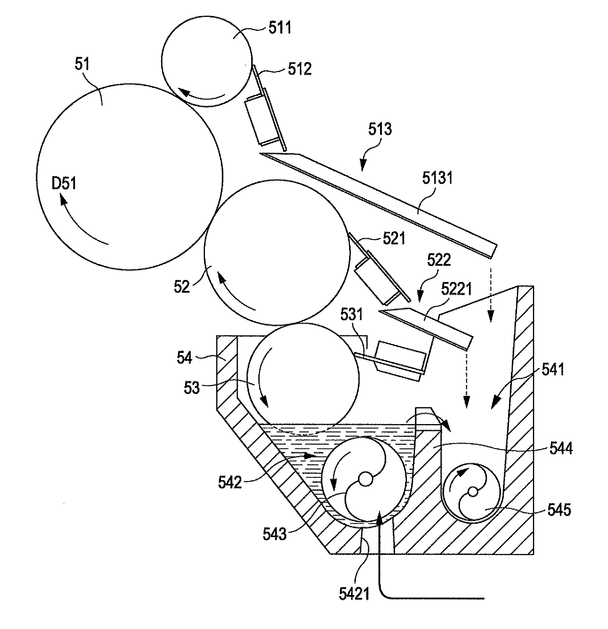
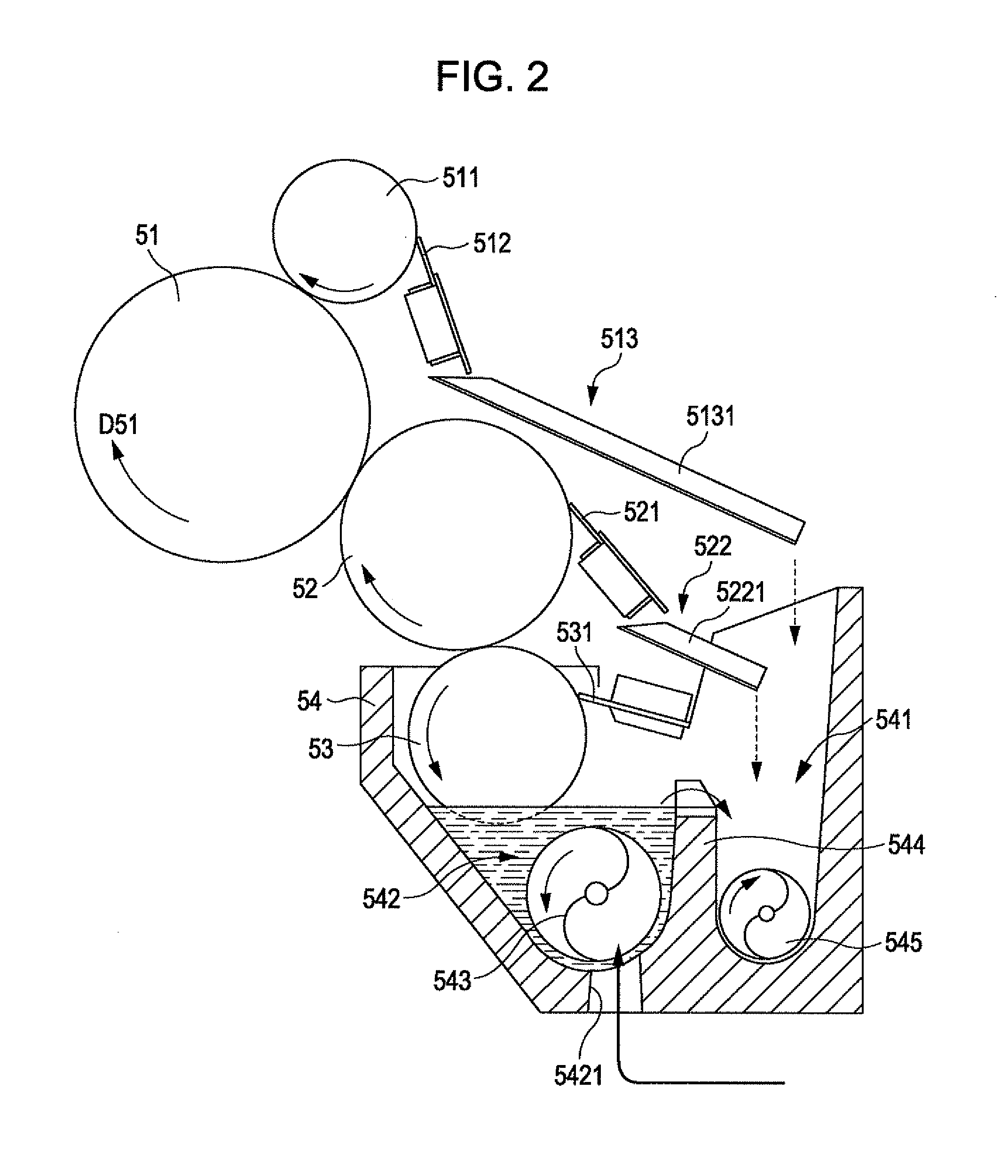
[0006]It is an advantage of some aspects of the invention to provide a technique for favorably supplying a liquid developer to a developer bearing roller by driving, with high precision, a first supply roller, a second supply roller, and the developer bearing roller using two drive sources, in what is known as a three-roller structure developing apparatus and an image forming apparatus provided with such a developing apparatus, in which a liquid developer held in a developer receptacle serving as a reservoir unit is supplied to the developer bearing roller via the first supply roller and the second supply roller.
[0009]According to the inventions the developing apparatus and the image forming apparatus) configured in this manner, the liquid developer held in the reservoir unit is supplied to the second supply roller by the first supply roller, and is further supplied to the developer bearing roller from the second supply roller. Of these, the developer bearing roller and the second supply roller are driven by the first drive source, and thus error between the rotational velocities of the developer bearing roller and the second supply roller is reduced. Meanwhile, the first supply roller is driven by the second drive source, which is different than the first drive source, and thus the first supply roller can be driven at a different rotational velocity than the rotational velocity of the second supply roller; this makes it possible to adjust the amount of the liquid developer supplied to the developer bearing roller. In other words, the amount of the liquid developer supplied to the second supply roller from the first supply roller is adjusted based on the rotational velocity difference between the first supply roller and the second supply roller, which makes it possible to adjust the amount of the liquid developer supplied to the developer bearing roller from the second supply roller; this in turn makes it possible to apply the liquid developer to the developer bearing roller in a favorable manner.

Problems solved by technology

Here, adding another motor for rotationally driving the intermediate application roller will not only lead to an increase in the cost of the apparatus, but will make it necessary to take into consideration the effects of heat generated by the additional motor; this will in turn make it necessary to take measures with respect to the developing apparatus and, by extension, to the image forming apparatus that is provided with the stated developing apparatus.

Method used


Image

  • Developing Apparatus and Image Forming Apparatus
  • Developing Apparatus and Image Forming Apparatus
  • Developing Apparatus and Image Forming Apparatus

Examples


Embodiment Construction

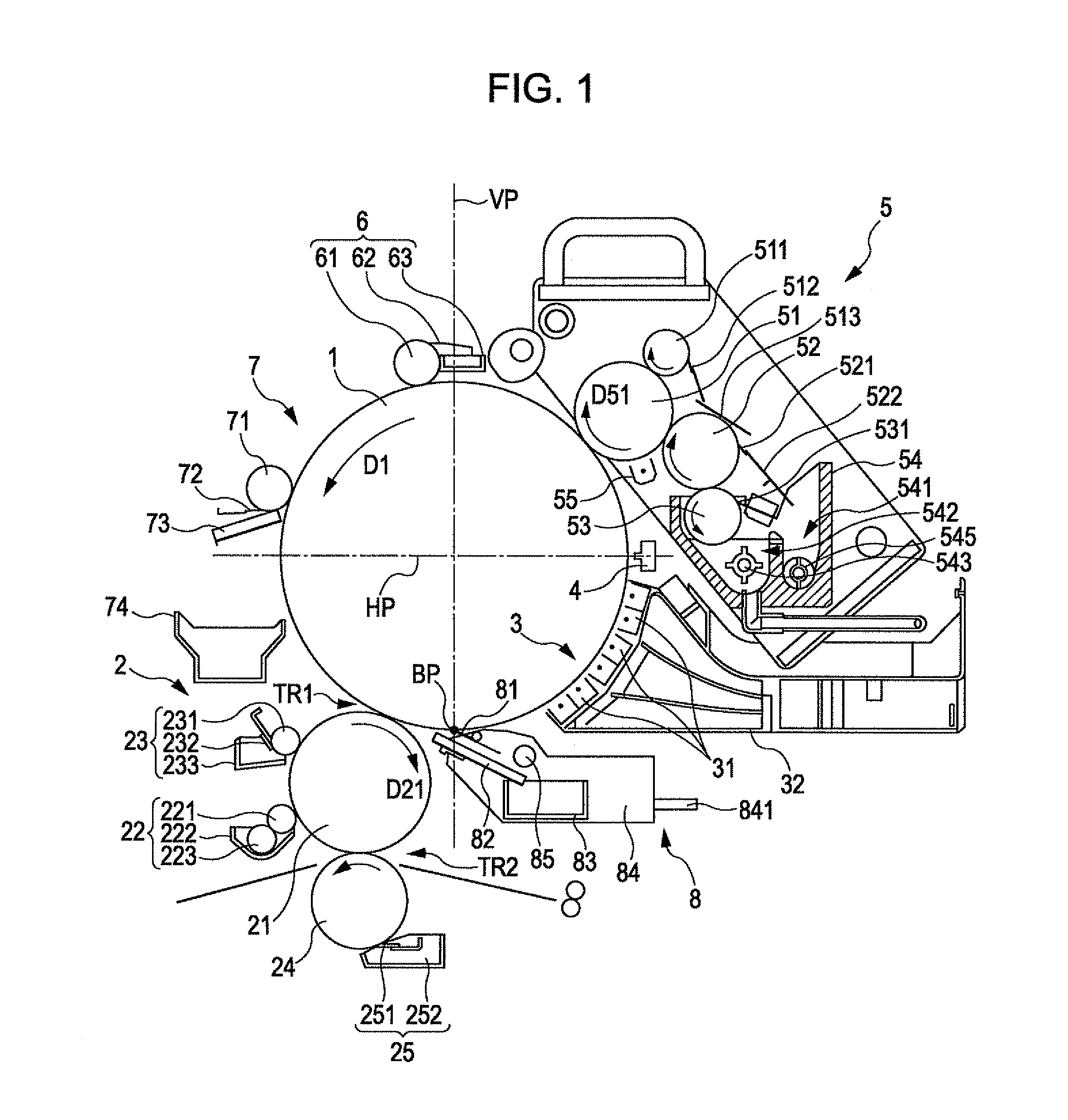
[0028]FIG. 1 is a diagram illustrating an image forming apparatus provided with a first embodiment of a developing apparatus according to the invention. This image forming apparatus has what is known as a “lower transfer structure”, in which an image borne upon a photosensitive drum 1 is transferred to a blanket roller 21 in a primary transfer unit 2 and the image transferred to the blanket roller 21 is further transferred onto transfer paper, the transfer process occurring below an imaginary horizontal plane HP that passes through the rotational center of the photosensitive drum 1. Note that, as will be described later, the image forming apparatus in FIG. 1 forms a single-color toner image and transfers that image onto the transfer paper, but it is also possible to configure a color printing system in which a plurality (for example, four) of such apparatuses are provided in an array. Of course, the apparatus shown in FIG. 1 also functions independently as a monochromatic image form...


PUM


Abstract

A driving force produced by a first driving motor is transmitted to a developing roller and an intermediate application roller by a first drive transmission unit, and the developing roller and the intermediate application roller are rotated as a result. The developing roller and the intermediate application roller thus take the first driving motor as a drive source, and receive the driving force from the first driving motor via the same first drive transmission unit. As a result, the phases of the fluctuation in a rotational component of the first driving motor and the cyclic fluctuation of gear interlocking match, which reduces a rotational velocity difference between the developing roller and the intermediate application roller.

Description

BACKGROUND[0001]1. Technical Field[0002]The present invention relates to developing apparatuses that develop images using a liquid developer containing toner and a carrier liquid, and to image forming apparatuses provided with such developing apparatuses.[0003]2. Related Art[0004]At present, liquid developer-type image forming apparatuses, in which a toner image is formed by forming an electrostatic latent image upon a charged photosensitive member and the electrostatic latent image is developed using a liquid developer in which toner is dispersed throughout a carrier liquid, are in practical use. For example, with a developing apparatus that is employed in the image forming apparatus according to JP-A-2009-204973 (in particular, FIG. 2), a developer receptacle is provided with a supply unit that contains a liquid developer to be borne on a developing roller that is rotationally driven by a developing roller motor. The liquid developer is supplied from the supply unit in the develop...

Claims


Application Information

Patent Timeline
IPC IPC(8): G03G15/10
CPCG03G15/104
Inventor MIYAZAWA, KAZUMASASAKI, TSUTOMUNISHIYAMA, KAZUHIROOKUMURA, NAOYUKI
Owner SEIKO EPSON CORP
Learn More