
Method, apparatus and system for testing an optical network

a technology of optical network and optical network, applied in the field of optical network technology, can solve problems such as service interruption, achieve the effects of reducing system processing complexity, reducing the influence of optical network test on communication, and saving re-registration and re-rang

Inactive Publication Date: 2012-09-20
APEX NET LLC
View PDF2 Cites 37 Cited by
  • Summary
  • Abstract
  • Description
  • Claims
  • Application Information

AI Technical Summary

Benefits of technology

[0004]Embodiments of the present invention provide a method, an apparatus and a system for testing an optical network, so as to protect a TC layer state machine of an ONU during a test, and avoid ONU disconnection and further services interruption due to a long-time test.
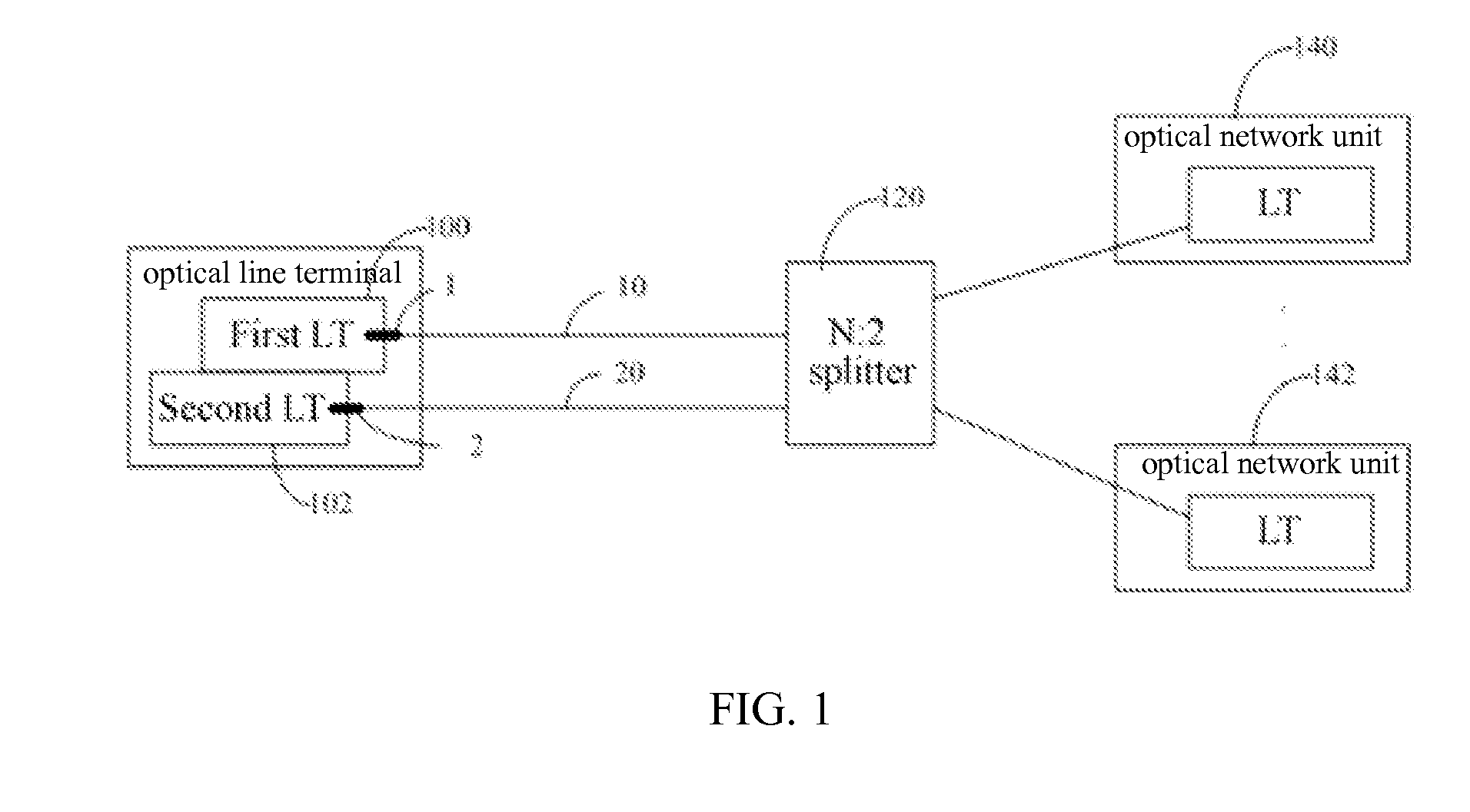
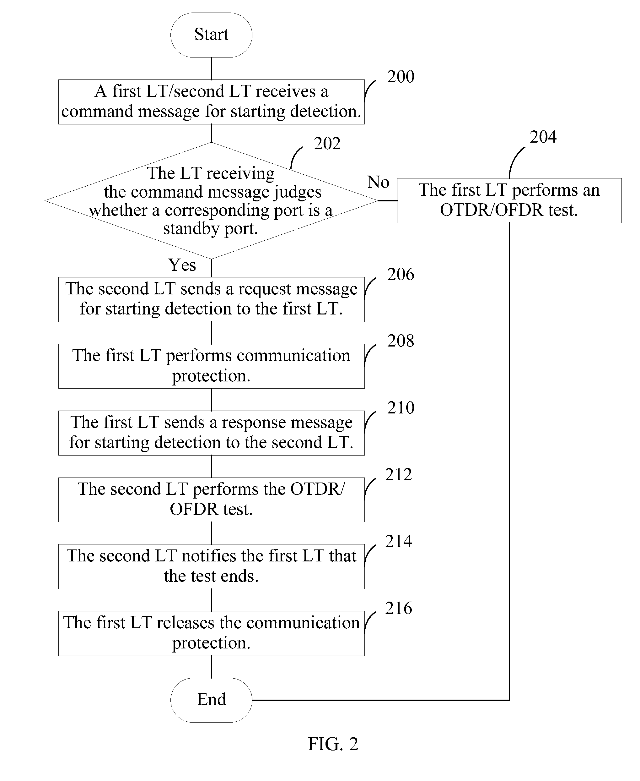
[0016]The method, apparatus and system for testing an optical network provided by the embodiments of the present invention are applicable to the integrated optical time domain reflectometer and an integrated optical frequency domain reflectometer. For example, an OLT integrated with an OTDR or an OFDR may adopt the method and apparatus for testing an optical network provided by the embodiments of the present invention. According to the embodiment of the present invention, the maximum test time of the single group test needs to be obtained; when the total test time is greater than the maximum test time of the single group test, the total test time is divided into at least two groups of single group test time that is not greater than the maximum test time, so as to ensure that the duration of each single group test does not exceed the maximum test time of the single group test. Therefore, the optical network equipment does not restore to an initial state, which saves time of re-registration and re-ranging of the optical network equipment. In this way, the optical network equipment may not be disconnected due to the optical network test, which ensures normal operation of services in the optical network, decreases system processing complexity while reduces the influence of the optical network test on communication, and improves customer satisfaction.

Problems solved by technology

However, the ONU is easily disconnected during the test, thereby causing service interruption.

Method used


Image

  • Method, apparatus and system for testing an optical network
  • Method, apparatus and system for testing an optical network
  • Method, apparatus and system for testing an optical network

Examples


embodiment 1

[0146]An embodiment of the present invention provides a method for testing an optical network, applicable to an integrated optical time domain reflectometer or optical frequency domain reflectometer, which includes, but is not limited to, a situation of integrating an optical time domain reflectometer or an optical frequency domain reflectometer in optical central office equipment (such as an OLT). As shown in FIG. 9, the method for testing an optical network specifically includes the following.

[0147]Step 901: Obtain a maximum test time of a single group test, where the maximum test time of the single group test according to this embodiment is as follows: if a continuous test time of a group of tests is within the maximum test time, optical terminal equipment (such as an ONU or an ONT) does not restore to an initial state; and if the continuous test time of a group of tests exceeds the maximum test time, the optical terminal equipment restores to the initial state.

[0148]Step 902: Wh...

embodiment 2

[0155]It is taken as an example in this embodiment that an OTDR or OFDR is integrated in an OLT and a user side interface is provided for a user through an ONU to illustrate a method for testing an optical network applicable to an integrated OTDR or OFDR provided in the embodiment of the present invention. As shown in FIG. 11A and FIG. 11B, the method specifically includes the following.

[0156]Step B01: An OLT receives a command message for starting passive optical network monitoring.

[0157]The command message may be delivered to the OLT by a network management system through a SNMP protocol, or may be input by maintenance personnel on the OLT through a command line, and may also be triggered by an internal timer of the OLT.

[0158]The command message may include port information of a port to be monitored, a test type, a total test time, a test pulse width and a measuring range. The port information of a port to be tested may include a block number, a slot number and a port number of th...

embodiment 3

[0193]An embodiment of the present invention further provides an apparatus for testing an optical network, applicable to an integrated optical time domain reflectometer or an integrated optical frequency domain reflectometer, which includes, but is not limited to, a situation of integrating an optical time domain reflectometer or an optical frequency domain reflectometer in optical central office equipment (such as an OLT). As shown in FIG. 12, the apparatus for testing an optical network includes a monitoring unit 51, an obtaining unit 52, a grouping unit 53, a test unit 54, an instruction unit 55 and a processing unit 56.

[0194]The monitoring unit 51 is configured to monitor a loss of signal / loss of frame alarm of a port to be detected before obtaining a maximum test time of a single group test. If the LOS or LOF alarm is monitored, it indicates that all ONUs under the port to be tested are disconnected and a problem of preventing the ONUs from restoring to an initial state during ...


PUM


Abstract

Embodiments of the present disclosure describe a method and an apparatus for testing an optical network, which may be applicable to an integrated OTDR and the field of optical network technologies. The method includes obtaining a maximum test time of a single group test; dividing a total test time into at least two groups of single group test time that is not greater than the maximum test time when the total test time is greater than the maximum test time of the single group test; performing the single group tests in sequence according to each single group test time; and instructing optical network equipment to restore to a normal working state when the single group test time corresponding to each single group test ends.

Description

CROSS-REFERENCE TO RELATED APPLICATIONS[0001]This application is a continuation of International Application No. PCT / CN 2010 / 079213, filed on Nov. 29, 2010, which claims priority to Chinese Patent Application No. 200910188476.1, filed on Dec. 1, 2009, and Chinese Patent Application No. 200910260757.3, filed on Dec. 31, 2009, all of which are hereby incorporated by reference in their entireties.FIELD OF THE INVENTION[0002]The present invention relates to the field of optical network technologies, and in particular, to a method, an apparatus and a system for testing an optical network.BACKGROUND OF THE INVENTION[0003]At present, an OTDR (Optical Time Domain Reflectometer, optical time domain reflectometer) is test equipment widely applied in optical fiber networks. A basic principle of the OTDR is sending probe light to an optical fiber, and receiving a reflected / scattered optical signal on an optical fiber link. Through analyzing and processing a transmitted signal and the received r...

Claims


Application Information

Patent Timeline
IPC IPC(8): H04B10/08H04B10/071
CPCH04L43/50H04L12/2697H04B10/071
Inventor YIN, JINRONGYANG, SULIN
Owner APEX NET LLC
Learn More