Gear Lever Locking Device

a technology of locking device and lever, which is applied in the direction of mechanical control device, gearing control, restricting/preventing/returning movement of parts, etc., can solve the problem of inability to use mechanical tools to fasten screws with screw guards

Inactive Publication Date: 2012-09-13
KANTAJARANITI KAMOL +2
View PDF4 Cites 2 Cited by
  • Summary
  • Abstract
  • Description
  • Claims
  • Application Information

AI Technical Summary

Benefits of technology

[0031]The first stud is slid out of the locked position and away from the trigger of the micro switch when the gear lever locking device is moved to an unlocked position, thereby completing the electrical circuit of the micro switch. Electricity is then supplied to the anti-start system, thereby allowing the engine to start and the regular movement of the gear lever.

Problems solved by technology

However, it is impossible to use the mechanical tools to fasten the screws with the screw guards if the gear lever locking device is in the locked position.

Method used


Image

  • Gear Lever Locking Device
  • Gear Lever Locking Device
  • Gear Lever Locking Device

Examples


Embodiment Construction

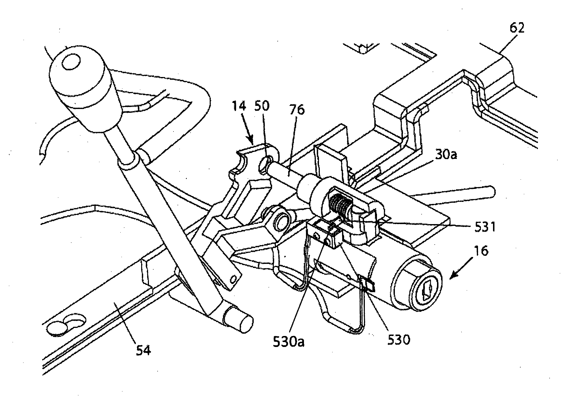
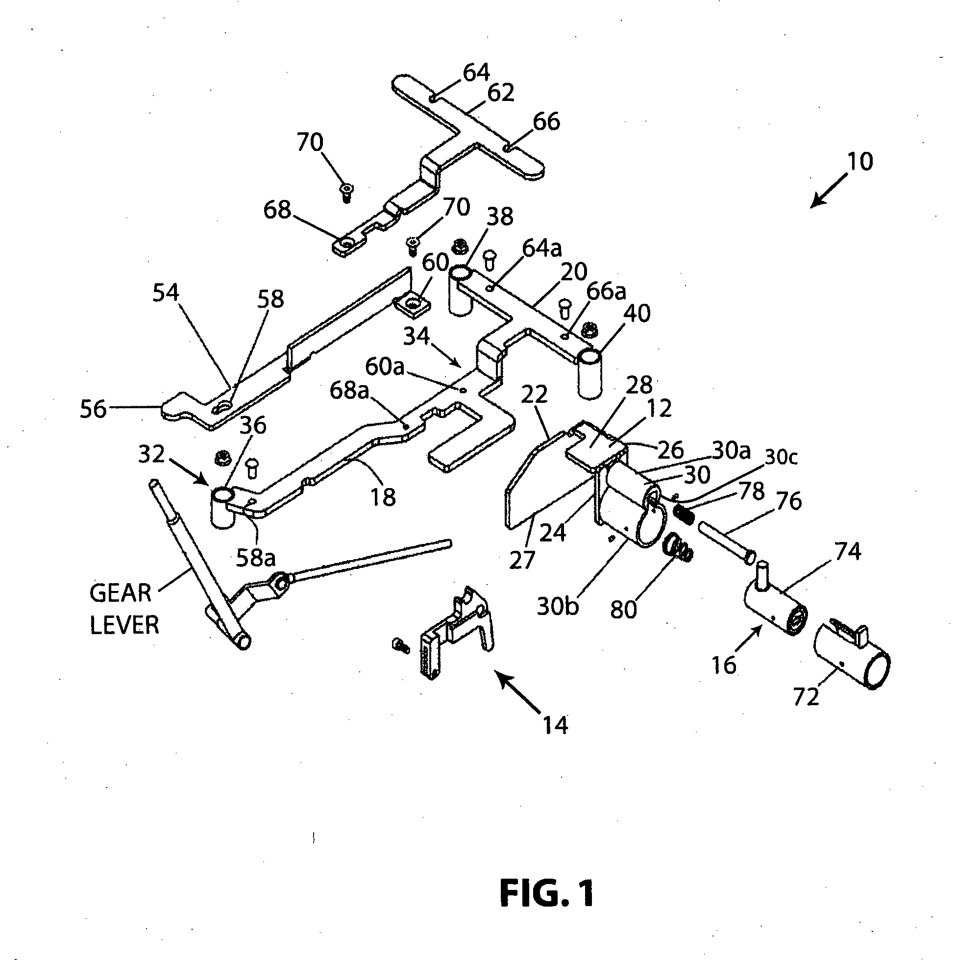
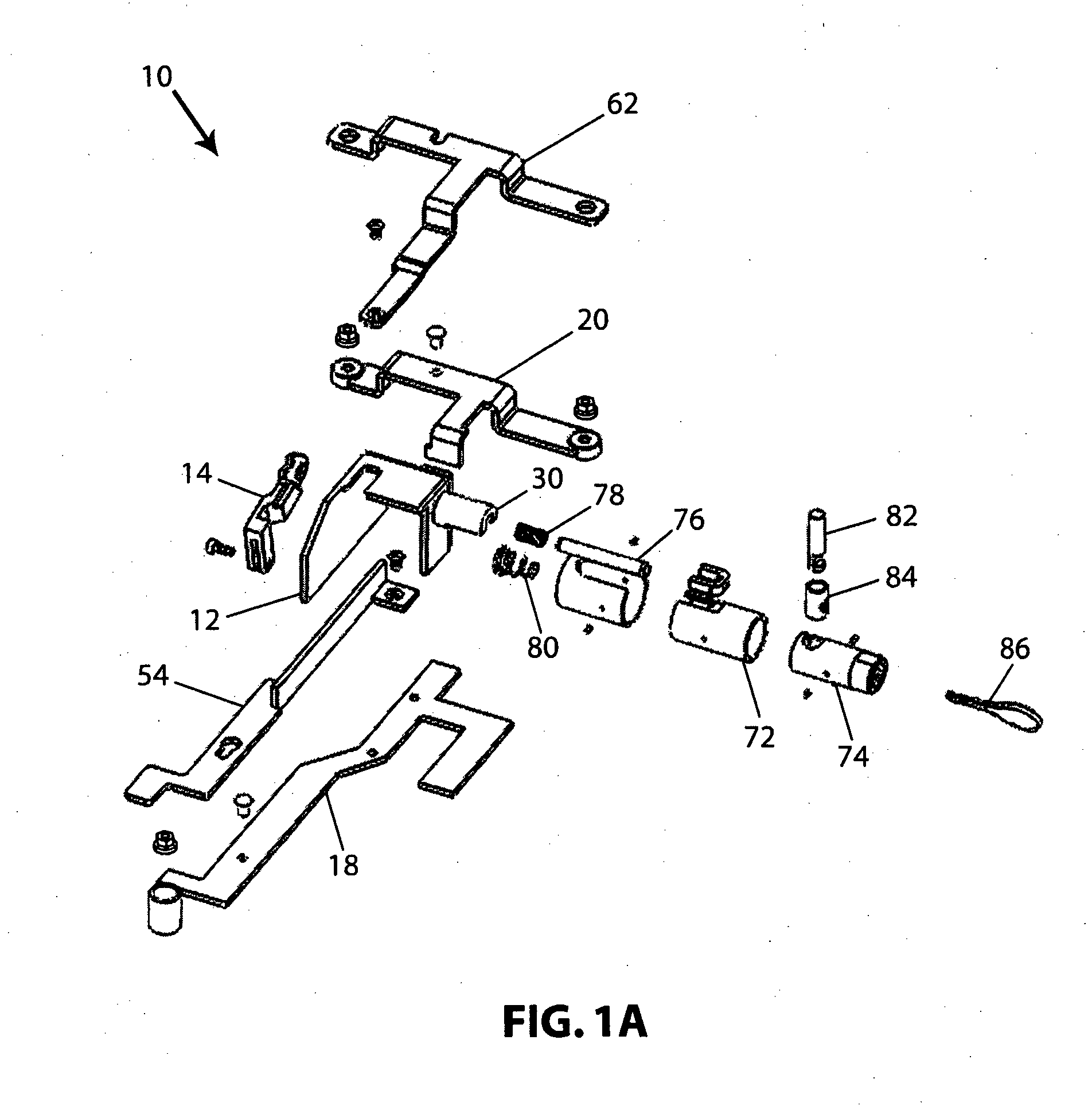
[0069]Reference will now be made in detail to the preferred embodiments of the invention illustrated in the accompanying drawings. Wherever possible, the same or like reference numbers will be used throughout the drawings to refer to the same or like features. It should be noted that the drawings are in simplified form and are not drawn to precise scale. In reference to the disclosure herein, for purposes of convenience and clarity only, directional terms such as top, bottom, above, below and diagonal, are used with respect to the accompanying drawings. Such directional terms used in conjunction with the following description of the drawings should not be construed to limit the scope of the invention in any manner not explicitly set forth. Additionally, the term “a,” as used in the specification, means “at least one.” The terminology includes the words above specifically mentioned, derivatives thereof, and words of similar import.

[0070]In a first preferred embodiment, the present in...


PUM


Abstract

A gear lever locking device to be installed inside a gear lever cover panel is characterized in that it comprises an auxiliary connector transverse stud and a gear lever connector which is slidable in accordance with the movement of a gear lever. On an auxiliary connector, there is provided a plurality of stud holes for use with a gear lever transverse stud having a stud end pushing mechanism. The stud end pushing mechanism receives the force exerted from a locking mechanism by a pressing means. The gear lever locking device according to the present invention includes screw guards and a cover wall that have been designed to cover a locking mechanism installation portion to prevent any removal of fastening screws or a gear sling, to prevent disassembling or breaking of the locking mechanism of the gear lever locking device to improve safety.

Description

BACKGROUND OF THE INVENTION[0001]The present invention relates generally to a gear lever locking mechanism for a vehicle. In particular, the present invention relates to a gear lever locking mechanism mountable directly onto a gear lever housing frame of a vehicle to lock movement of the vehicle's gear lever.[0002]Conventional gear lever locking devices include a mechanism for locking a typical gear lever of an automobile. The typical gear lever locking device is a loop member for use in locking the gear lever only in one particular position according to the installation position. In addition, the aforementioned gear lever locking device's loop member may be unlocked by an unlocking key system. However, conventional gear lever locking devices have an operational drawback. That is, if a user wants to shift the locking position of the gear lever from the parking position (P position) to the neutral position (N position), it is impossible to shift the gear lever to the position that me...

Claims


Application Information

Patent Timeline
Patent Type & Authority Applications(United States)
IPC IPC(8): G05G5/28B60R25/10F16H57/00
CPCB60R25/066F16H59/02Y10T74/20091Y10T70/5708Y10T70/5934
Inventor KANTAJARANITI, KAMOLTIEMSIRIWAT, SOMCHAI
Owner KANTAJARANITI KAMOL
Why Eureka
Try Eureka