
Spacecraft payload positioning with respect to a virtual pivot point

Active Publication Date: 2012-09-13
SPACE SYST LORAL INC
View PDF11 Cites 5 Cited by
  • Summary
  • Abstract
  • Description
  • Claims
  • Application Information

AI Technical Summary

Benefits of technology

[0009]In an embodiment, the actuator may be located proximate to a supported edge of the payload element. Advantageously, the actuator provides a mechanical advantage (effectively a gear ratio) that increases the effective stiffness of an associated drive mechanism and reduces a step size of the drive mechanism, thereby increasing payload element positioning resolution.

Problems solved by technology

For spacecraft requiring larger reflectors and / or more stringent pointing requirements, however, such techniques are problematic.
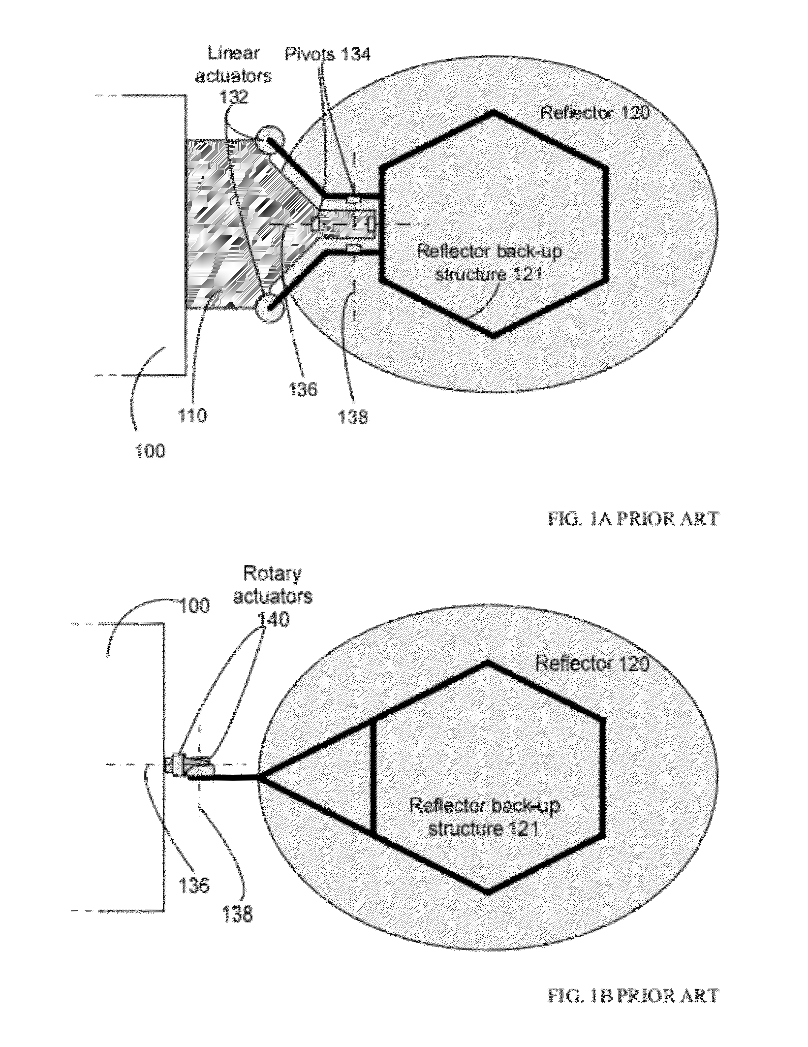
This results in a low deployed natural frequency, and, consequently pointing performance degradation, because the moment of inertia of reflector 120 is large, particularly about axis of rotation 138.
However, this increases the inertia about the deployment hinge and puts the actuators in a severe thermal environment.
Moreover, locating the actuators behind or at an edge of reflector 120, results in rotation of reflector 120 about a point substantially distant from an RF focal point of reflector 120, resulting in defocusing of payload beam and consequent performance degradation.

Method used


Image

  • Spacecraft payload positioning with respect to a virtual pivot point
  • Spacecraft payload positioning with respect to a virtual pivot point
  • Spacecraft payload positioning with respect to a virtual pivot point

Examples


Embodiment Construction

[0029]Specific exemplary embodiments of the invention will now be described with reference to the accompanying drawings. This invention may, however, be embodied in many different forms, and should not be construed as limited to the embodiments set forth herein. Rather, these embodiments are provided so that this disclosure will be thorough and complete, and will fully convey the scope of the invention to those skilled in the art.

[0030]It will be understood that when an element is referred to as being “connected” or “coupled” to another element, it can be directly connected or coupled to the other element, or intervening elements may be present. Furthermore, “connected” or “coupled” as used herein may include wirelessly connected or coupled. It will be understood that although the terms “first” and “second” are used herein to describe various elements, these elements should not be limited by these terms. These terms are used only to distinguish one element from another element. Thus...


PUM


Abstract

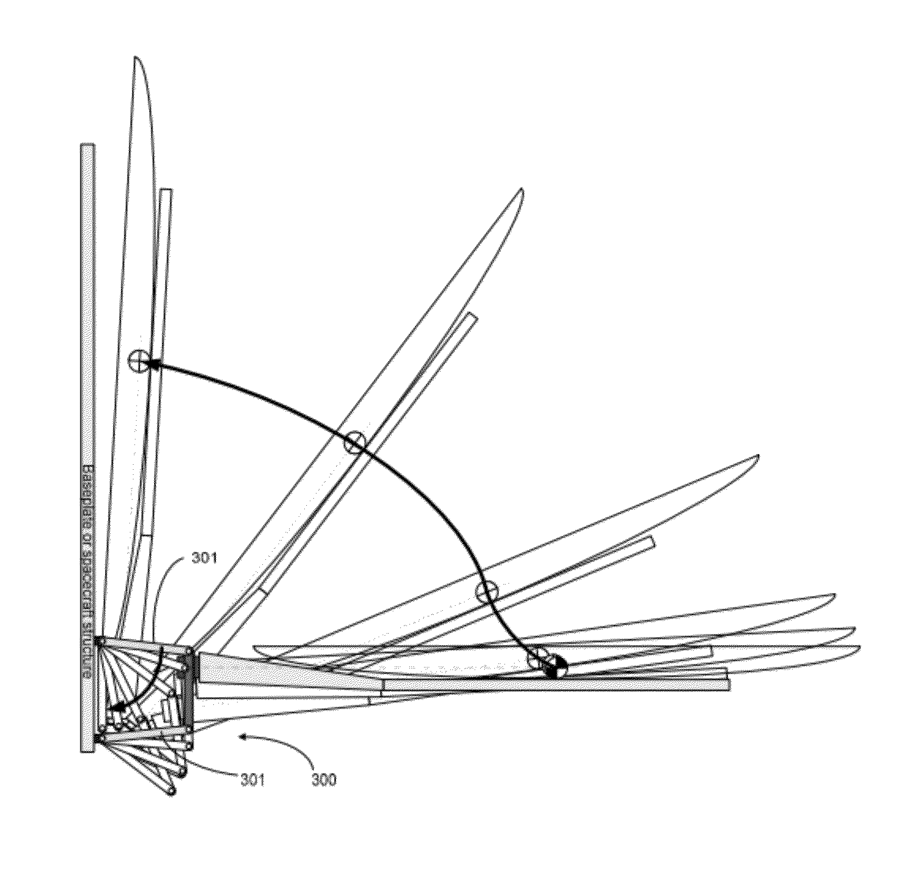
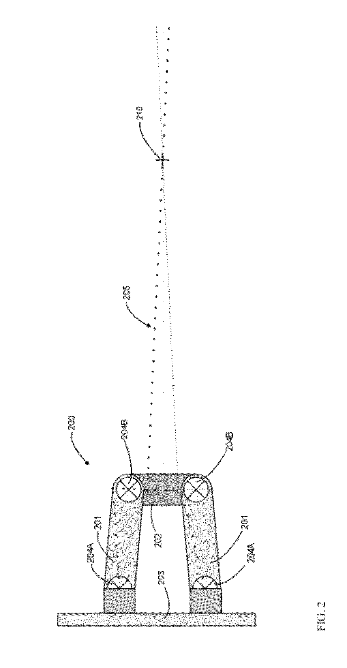
A spacecraft payload element is rotated by a mechanism about virtual pivot point (VPP) substantially distant from the mechanism. The mechanism couples the payload element to a spacecraft main body structure, and has a four-bar linkage configured to rotate the payload element about a virtual pivot point (VPP). The VPP may be proximate to the focus or center of gravity (cg) of the payload element. Rotation of the payload element about the VPP may be controlled by linear or rotary actuators which drive the four-bar linkage. The four-bar linkage may be configured to provide a mechanical advantage to the actuator.

Description

TECHNICAL FIELD[0001]This invention relates generally to spacecraft and, in particular, to methods and apparatus for providing payload positioning with respect to a virtual pivot point.BACKGROUND OF THE INVENTION[0002]The assignee of the present invention manufactures and deploys spacecraft for communications and broadcast services. To meet market demands for advanced services from such spacecraft, spacecraft payloads of increased size and improved pointing performance are required. For example, there is a demand for increased aperture antenna reflectors, having diameters of three meters or greater, and larger, more complex, radio frequency (RF) feed arrays. A payload element, such as, for example, an antenna reflector, and / or an RF feed array, often require one or more positioning mechanisms configured to provide for (i) initial deployment of the payload element from a stowed launch position to an (on-orbit) operating position, and / or (ii) on-orbit steering of the reflector or feed...

Claims


Application Information

Patent Timeline
IPC IPC(8): B64G1/66G05G1/00B64G1/22
CPCB64G1/66H01Q1/288Y10T74/20B64G1/222H01Q15/161
Inventor FRANCIS, COLIN M.
Owner SPACE SYST LORAL INC
Learn More