Tape cartridge

a technology of tape cartridges and tapes, applied in the field of tape cartridges, can solve the problems of components that push through or otherwise damage the surface of the box, decrease the throughput speed, increase the likelihood of such damage, etc., and achieve the effect of reducing the biasing for

Active Publication Date: 2012-09-13
SIGNODE IND GRP
View PDF5 Cites 6 Cited by
  • Summary
  • Abstract
  • Description
  • Claims
  • Application Information

AI Technical Summary

Benefits of technology

[0008]According to another example, a tape cartridge includes a mounting plate and an application roller arm assembly. The application roller arm assembly further includes a support arm movably coupled to the mounting plate, an application roller coupled to the support arm, a coupling coupled to the support arm, a biasing element coupled to the coupling and the mounting plate, and a mechanism for reducing a biasing force from the biasing element. The mechanism is coupled to the support arm and the mounting plate.
[0009]Another example is directed a case processing system that includes a sensor for detecting the presence of a case to be sealed, a controller coupled to the sensor, and a tape cartridge coupled to the controller. The tape cartridge includes a first application roller arm assembly, a second application roller arm assembly, and a biasing element for biasing the first and second application roller arm assemblies to a start position. The tape cartridge also includes a mechanism for reducing a biasing force from the biasing element. In response to the sensor detecting the case, the controller actuates the mechanism to reduce the biasing force from the biasing element and allow the first and second application roller arm assemblies to move to an end position with minimal force thereon. In response to the sensor no longer detecting the case, the controller de-actuates the mechanism to allow the biasing force to return the first and second application roller arm assemblies to the start position.

Problems solved by technology

One issue with known tape cartridges is that the biasing force required for the proper operation of the front application roller arm assembly, the rear application roller arm assembly, and / or the cutting mechanism may cause such components to push through or otherwise damage a surface of the box as they come into contact therewith.
Consequently, the damaged box may have to be discarded and the contents of the box repackaged, which results in decreased throughput speeds.
The likelihood of such damage occurring is increased when there is a void between the contents of the box and the box itself.
However, such practice is often curtailed to generate savings in material cost and production time.
Further, the use of lesser quality boxes, such as recycled boxes, may also adversely affect the integrity of the boxes and increase the likelihood of the tape cartridge damaging the box.

Method used


Image

  • Tape cartridge
  • Tape cartridge
  • Tape cartridge

Examples


Embodiment Construction

[0019]While the present disclosure is susceptible of embodiment in various forms, there is shown in the drawings and will hereinafter be described one or more embodiments with the understanding that the present disclosure is to be considered illustrative only and is not intended to limit the disclosure to any specific embodiment described or shown.

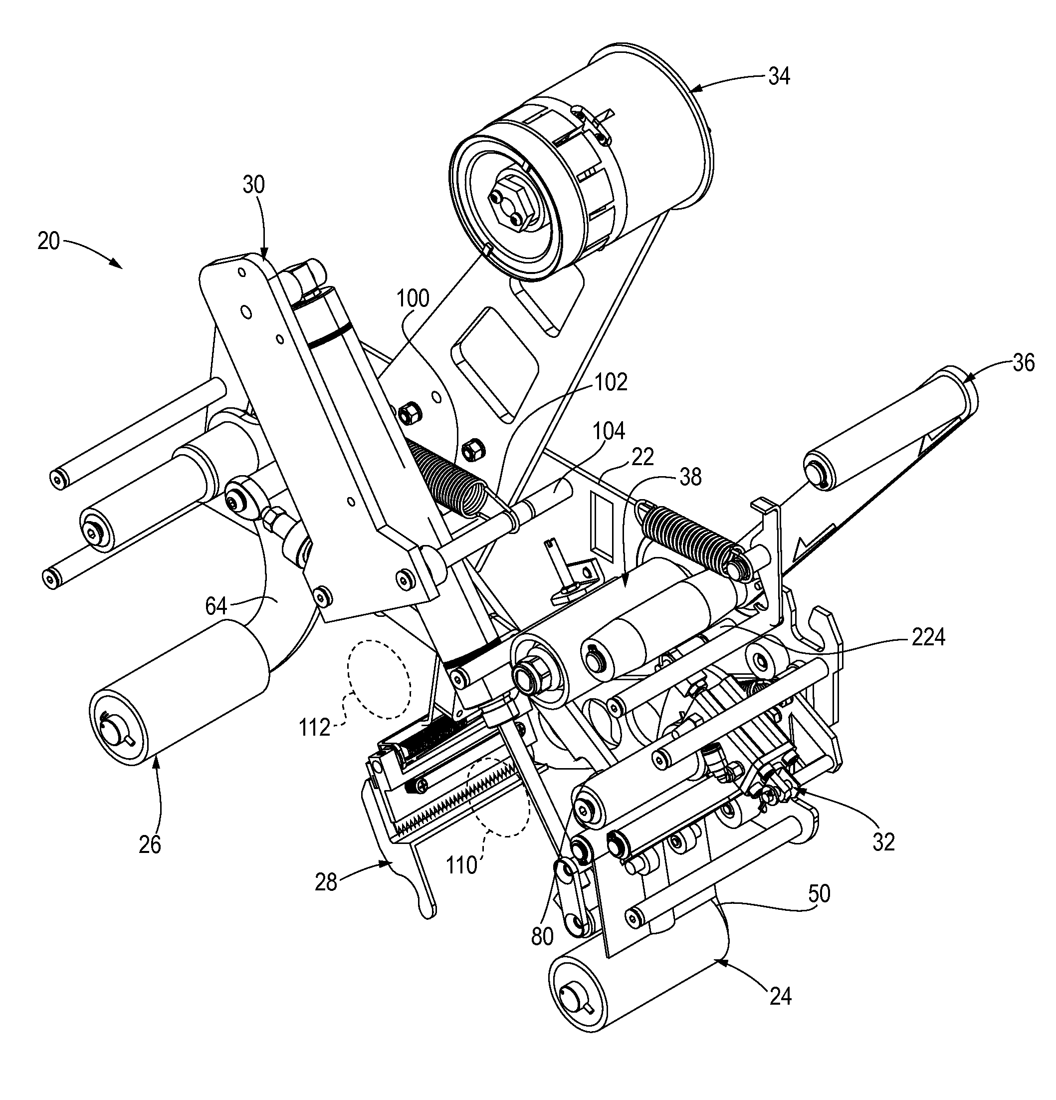
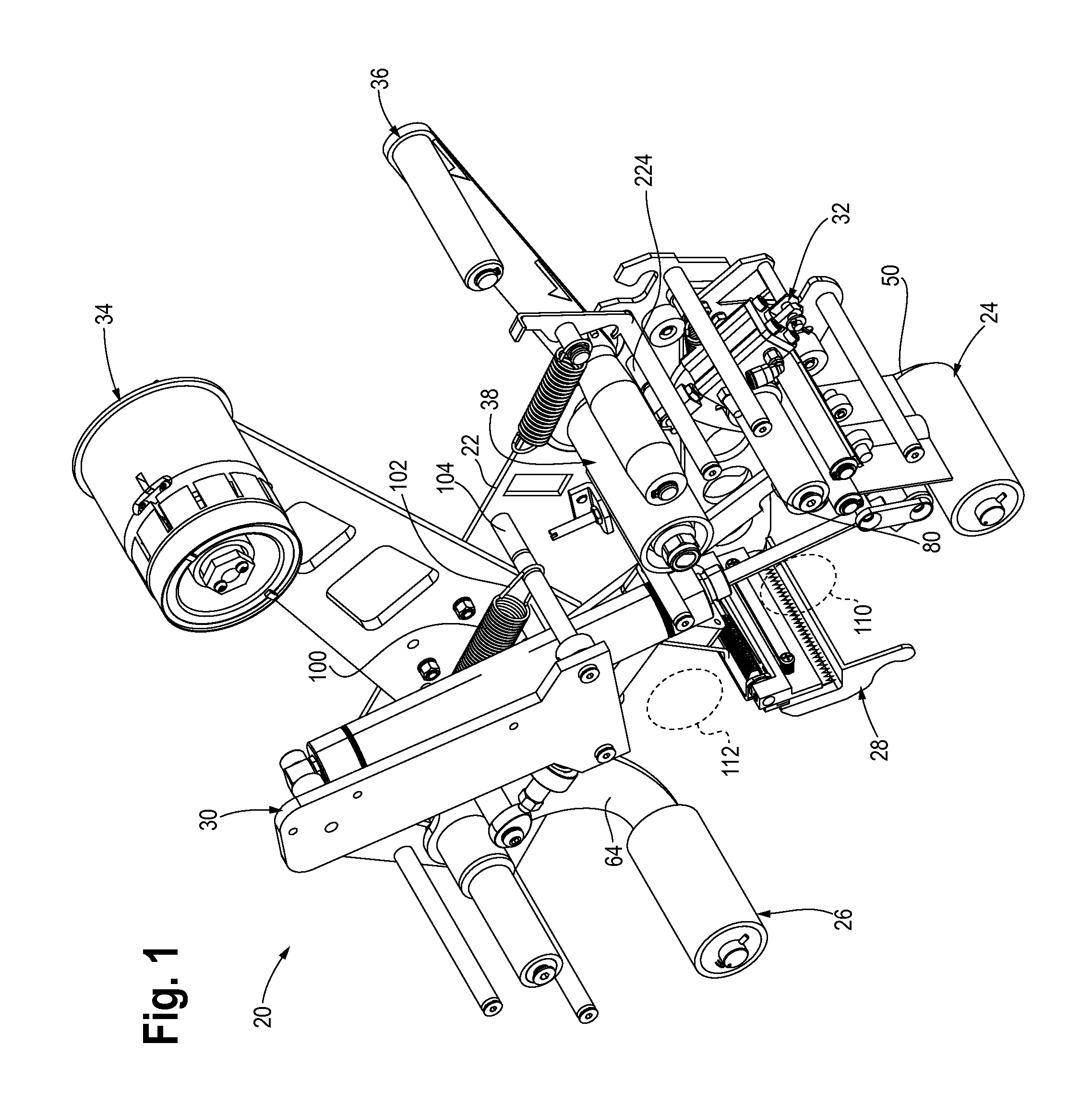
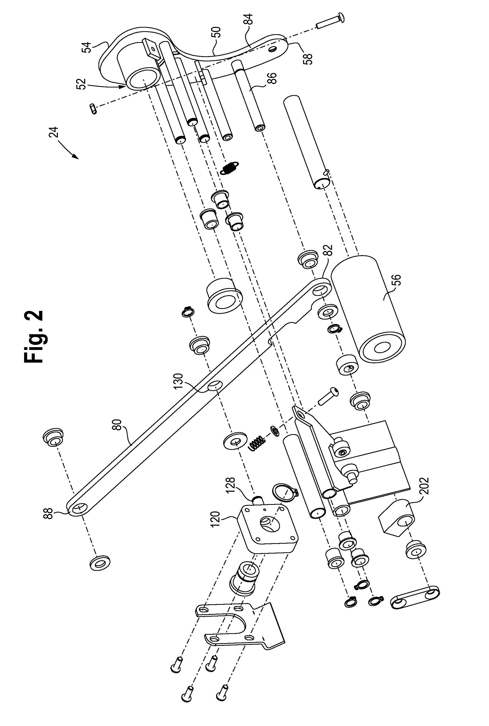
[0020]Referring now to FIGS. 1-6, a tape cartridge 20 is shown that includes a main mounting plate 22 to which are mounted, directly or indirectly, a front application roller arm assembly 24, a rear application roller arm assembly 26, and a cutting mechanism or knife assembly 28. A first mechanism 30 for reducing a biasing force is coupled to the front application roller arm assembly 24 and a second mechanism 32 for reducing a biasing force is coupled to the cutting mechanism assembly 28. In addition, a tape core assembly 34, a tape tension arm assembly 36, and a tension roller assembly 38 are coupled to the main mounting plate 22.

[0021]In...


PUM

PropertyMeasurementUnit
biasing forceaaaaaaaaaa
forceaaaaaaaaaa
pressure sensitiveaaaaaaaaaa

Abstract

An application roller arm assembly for use with a tape cartridge includes a support arm having first and second ends and adapted to be coupled to the tape cartridge. The application roller arm assembly also includes a coupling for a biasing element. The coupling is coupled to the support arm and the biasing element is configured to be coupled to the coupling and the tape cartridge. Further, the application roller arm assembly includes a mechanism for reducing a biasing force from the biasing element. The mechanism is configured to be coupled the support arm and the tape cartridge.

Description

CROSS-REFERENCE TO RELATED APPLICATION DATA[0001]This application claims the benefit of priority of Provisional U.S. Patent Application Ser. No. 61 / 451,722, filed Mar. 11, 2011, the entirety of which is incorporated herein by reference.BACKGROUND OF THE DISCLOSURE[0002]Tape cartridges can be utilized to apply a packing tape, such as pressure sensitive tape, to a surface of a case or box to be sealed. In one example, the tape cartridge rides on a surface of the case, such as a top and / or bottom surface, generally along a seam formed between opposing flaps of the case that are folded over. The tape cartridge applies packing tape along the seam as the case is conveyed past the tape cartridge to seal the case. The tape cartridge may include a front application roller arm assembly for applying the packing tape to a front surface and the top / bottom surface of the case, a cutting mechanism for cutting or severing the tape as the case is conveyed past the tape cartridge, and a rear applicat...

Claims


Application Information

Patent Timeline
Patent Type & Authority Applications(United States)
IPC IPC(8): B26D5/00B29C65/50
CPCB65B51/067B65H35/0013Y10T156/17B31B3/00Y10T156/12B65H2601/25B31B2100/00
Inventor MENTA, WILLIAM J.FOX, BRYCE J.
Owner SIGNODE IND GRP
Why Eureka
Try Eureka