Sun visor for vehicles

a technology for vehicles and sunvisors, applied in the direction of roofs, superstructures, monocoque constructions, etc., can solve the problems of torque fluctuations and the inability of the support rod to retain its circular shape, so as to reduce the biasing force and improve the stability of torque generation.

Active Publication Date: 2013-05-16
KYOWA SANGYO
View PDF0 Cites 2 Cited by
  • Summary
  • Abstract
  • Description
  • Claims
  • Application Information

AI Technical Summary

Benefits of technology

[0006]Accordingly, it is an object of the invention to provide a technique for reducing biasing force acting upon a support rod, while securing a rotating torque to pivot sun visor body for a vehicle sun visor.
[0008]According to the preferred embodiment of the sun visor in this invention, as a characterizing feature, the sun visor includes a biasing and holding member that biases and holds the support rod only by three regions in a circumferential direction of the support rod. Preferably, the three regions that bias and hold the support rod are arranged generally equidistantly in the circumferential direction, but the arrangement of the three regions is not limited to this. According to this invention, with the construction in which the support rod is held at three points in the circumferential direction, a biasing force upon each of the three regions of the support rod can be reduced, while a rotating torque required to pivot the sun visor body with respect to the support rod can be secured. As a result, an effect of preventing deformation of the support rod or an effect of reducing the occurrence of creep can be obtained.
[0009]Further, according to the preferred embodiment of the sun visor in this invention, the biasing and holding member is formed by a leaf spring and integrally includes a support rod holding region and a biasing force generating region, and the biasing force generating region is for tried at a predetermined distance from the support rod holding region in a direction transverse to the axial direction of the support rod. Further, the biasing force generating region is designed as a mounting part for mounting the biasing and holding member to the sun visor body. Thus, the biasing force generating region also serves as a mounting part. Therefore, it is not necessary to provide an additional mounting part, so that the biasing and holding member can be provided with a rational structure of holding the support rod.
[0010]Further, according to a further embodiment of the sun visor in this invention, the support rod holding region has two clipping regions that are opposed to each other and elastically clip the support rod, and a third contact region that receives the support rod. The two clipping regions are arranged such that respective normal of each clipping region extends toward the third contact region to cross each other. With such a construction, a force of clipping the support rod is generated by the opposed clipping regions, and the support rod can be pressed against the third contact region by the clipping force. Thus, the support rod can be held at three points in the circumferential direction with stability.
[0012]As described above, according to the invention, a technique is provided for reducing a biasing force acting upon a support rod, while securing a rotating torque required to pivot a sun visor body, in a sun visor for vehicles. Further, stability of torque generation can be further improved. Other objects, features and advantages of the present invention will be readily understood after reading the following detailed description together with the accompanying drawings and the claims.

Problems solved by technology

Further, if the support rod is made of synthetic resin, the support rod may creep, so that the support rod cannot retain its circular shape and torque fluctuations may occur.

Method used


Image

  • Sun visor for vehicles
  • Sun visor for vehicles
  • Sun visor for vehicles

Examples


first representative embodiment

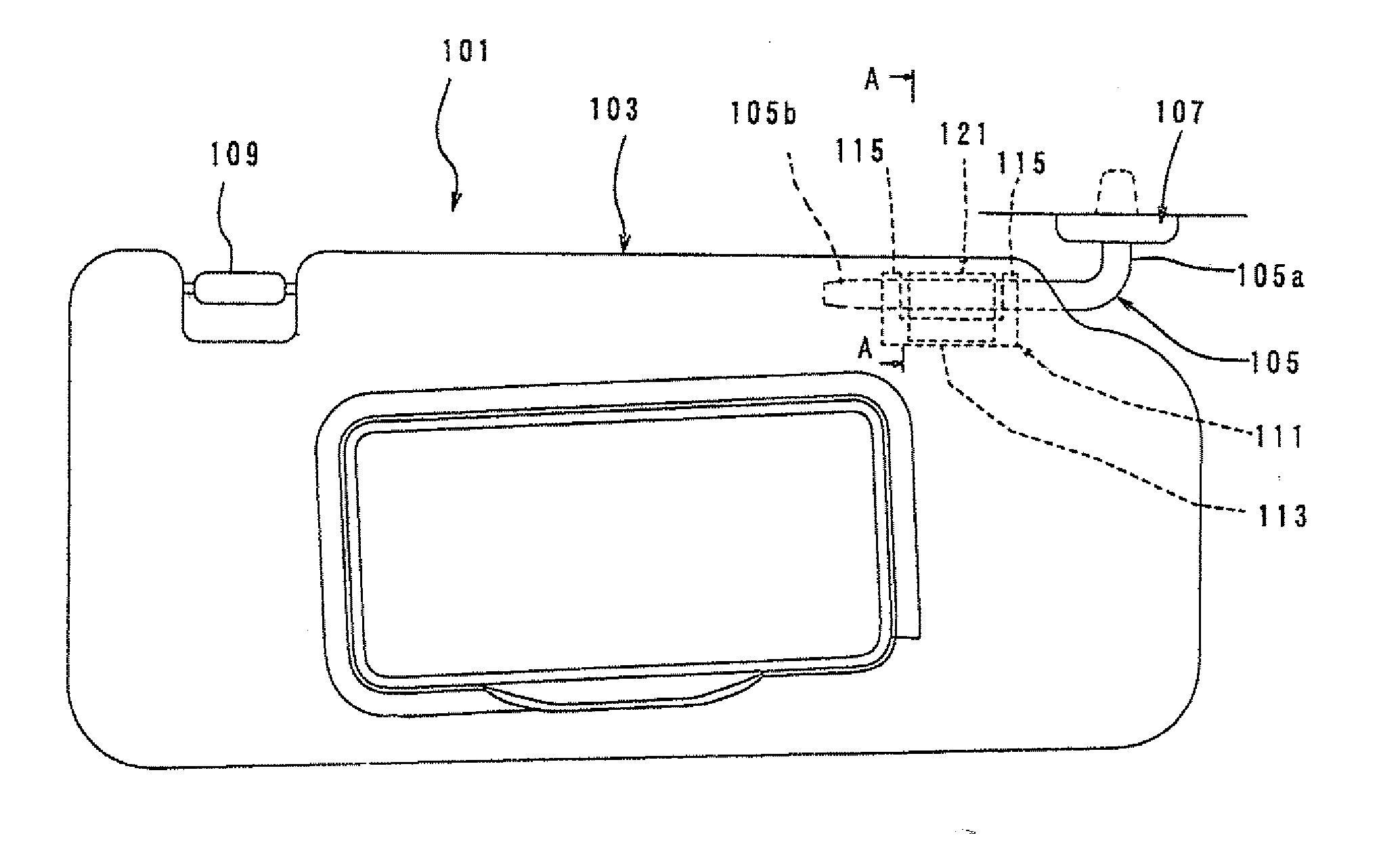
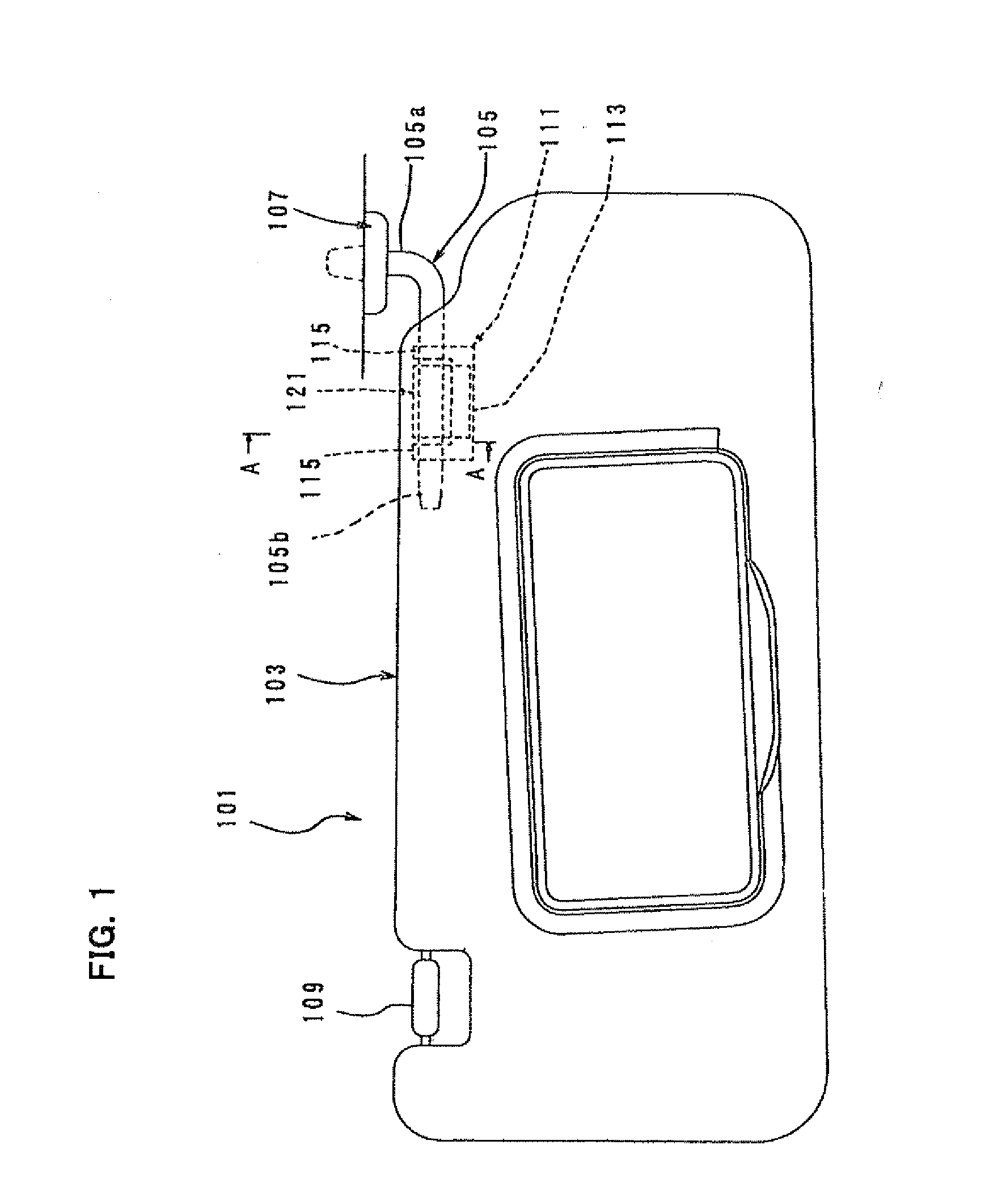
[0029]A sun visor 101 for vehicles according to a first representative embodiment of the invention is now described with reference to FIGS. 1 to 6. FIG. 1 schematically shows the entire structure of the sun visor 101. As shown in FIG. 1, the sun visor 101 mainly includes a sun visor body 103, a support rod 105 having a circular section and provided to mount the sun visor body 103 to the vehicle, and a mounting bracket 107. The support rod 105 has a generally L-shaped configuration and includes a generally vertically extending rod portion 105a and a generally horizontally extending rod portion 105b. The horizontal rod portion 105b of the support rod 105 is pivotally mounted to one corner of the upper edge of the sun visor body 103. The vertical rod portion 105a of the support rod 105 is pivotally mounted to the front corner of the interior roof surface of the vehicle via the mounting bracket 107. For the sake of convenience of explanation, in FIG. 1, the axial direction of the horizo...

second representative embodiment

[0052]The spring clip 121 according to a second embodiment of the present invention is now described with reference to FIGS. 7 to 11. FIGS. 7 and 8 are sectional views of the spring clip 121 according to this embodiment. FIG. 7 shows the working state in which the sun visor body 103 is placed in the use region, and FIG. 8 shows the storage state (locked state) in which the sun visor body 103 is placed in the storage region. Further, FIG. 9 is a perspective view of the spring clip 121, FIG. 10 is a front view of the spring clip and FIG. 11 is a rear view of the spring clip.

[0053]This embodiment is an alteration to the shape of the spring clip 121 of the above-described first embodiment. In this embodiment, the first arm 125 and the second arm 127 have respective extension arms 131, 133, and inner surfaces of the extension arms 131, 133 or third contact portions 131a, 133a contact the outer surface of the horizontal rod portion 105b. In the other points, it has the same construction a...

third embodiment

[0057]A spring clip 141 according to a third embodiment of the present invention is now described with reference to FIGS. 12 to 15. FIGS. 12 and 13 are perspective views of the spring clip 141, and FIG. 13 shows the state in which the horizontal rod portion 105b is held by the spring clip. Further, FIG. 14 is a side view of the spring clip 141, and FIG. 15 is a front view of the spring clip 141.

[0058]The spring clip 141 according to this embodiment is formed by bending a single leaf spring. The spring clip 141 mainly includes a generally inverted triangular central bend 143, and first and second arms 145, 147 extending downward from the central bend 143 and opposed to each other. The central bend 143 forms a holding region for holding the horizontal rod portion 105b. The triangular central bend 143 has first and second contact portions 143a, 143b formed by its opposed two sides, and a third contact portion 143c formed by its top side corresponding to the base of the triangular shape...


PUM


Abstract

A technique is disclosed for reducing a biasing force acting upon a support rod, while securing a rotating torque required to pivot a sun visor body, in a sun visor for vehicles. A sun visor for vehicles, in which a sun visor body 103 can pivot on a support rod 105, includes a biasing and holding member 121 that biases and holds the support rod 105 only by three regions in a circumferential direction of the support rod 105. The biasing and holding member 121 is formed by bending a single leaf spring and integrally includes a support rod holding region 125a, 127a, 129a and a biasing force generating region 123. The support rod holding region includes the three regions that surround an outer surface of the support rod, and the biasing force generating region is formed at a predetermined distance from the support rod holding region 125a, 127a, 129a in a direction transverse to the axial direction of the support rod 105. Further, the biasing force generating region 123 is designed as a mounting part for mounting the biasing and holding member 121 to the sun visor body 103.

Description

BACKGROUND OF THE INVENTION[0001]1. Field of the Invention[0002]The present invention relates to a sun visor for vehicles.[0003]2. Description of the Related Art[0004]A sun visor for vehicles includes a sun visor body and a support rod that can pivot with respect to the sun visor body. The sun visor body is mounted to an interior roof surface of a vehicle via the support rod and can pivot between a storage region along the roof surface and a use region along the windshield. A spring clip is provided inside the sun visor body and generates a predetermined rotating torque by biasing and holding the support rod from the outside when the sun visor body is pivoted. Such a sun visor for vehicles is disclosed, for example, in Japanese non-examined laid-open Patent Publication No. H5-246241. The known spring clip disclosed in this publication is formed by a leaf spring and obtains a rotating torque of the sun visor body by clipping the support rod from the outside.[0005]The known spring cli...

Claims


Application Information

Patent Timeline
Patent Type & Authority Applications(United States)
IPC IPC(8): B60J3/02
CPCB60J3/0217
Inventor ASAI, TAKASHI
Owner KYOWA SANGYO
Why Eureka
Try Eureka