Clamp device

a technology of cylinder and spring, which is applied in the direction of couplings, manufacturing tools, mechanical equipment, etc., can solve the problems of time and labor in assembling or maintaining the clamp device, and achieve the effect of efficiently producing the cylinder hole of the housing and the piston, and facilitating the disassembly and maintenance of the clamp devi

Active Publication Date: 2017-12-05
KOSMEK LTD (JP)
View PDF19 Cites 2 Cited by
  • Summary
  • Abstract
  • Description
  • Claims
  • Application Information

AI Technical Summary

Benefits of technology

[0014]In assembling the clamp device, when the return spring is mounted on the clamp arm, first, the return spring in a free state is disposed between the first hole of the housing and the second hole of the clamp arm. Next, the pressing bolt is screwed into the female screw hole from above and rotated to be fastened to compress the return spring. Thus, the mounting of the return spring is completed. In addition, in disassembling the clamp device, the pressing bolt is rotated relative to the female screw hole to be loosed, thereby returning the return spring from the compressed state described above to the free state or a state close to the free state. Thus, it is possible to easily dismount the return spring from the first hole and the second hole.
[0015]As described above, in assembling or disassembling the clamp device, the return spring is caused to come into the free state or a state close to the free state, whereby it is possible to make a biasing force thereof zero or decrease the biasing force. Thus, unlike the conventional art described above, a special tool

Problems solved by technology

Thus, the assembling or maintenance of th

Method used


Image

  • Clamp device
  • Clamp device
  • Clamp device

Examples


Embodiment Construction

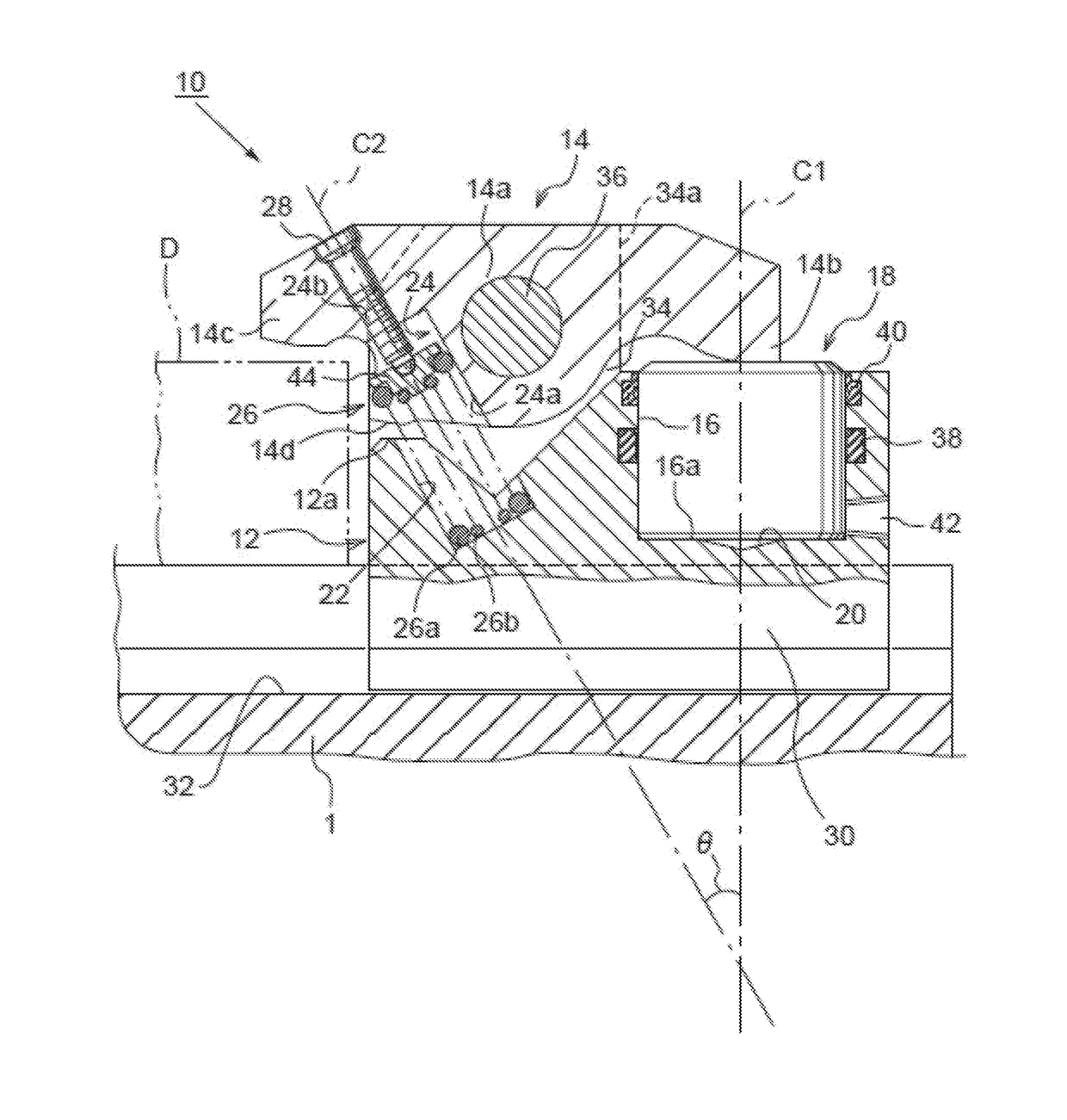
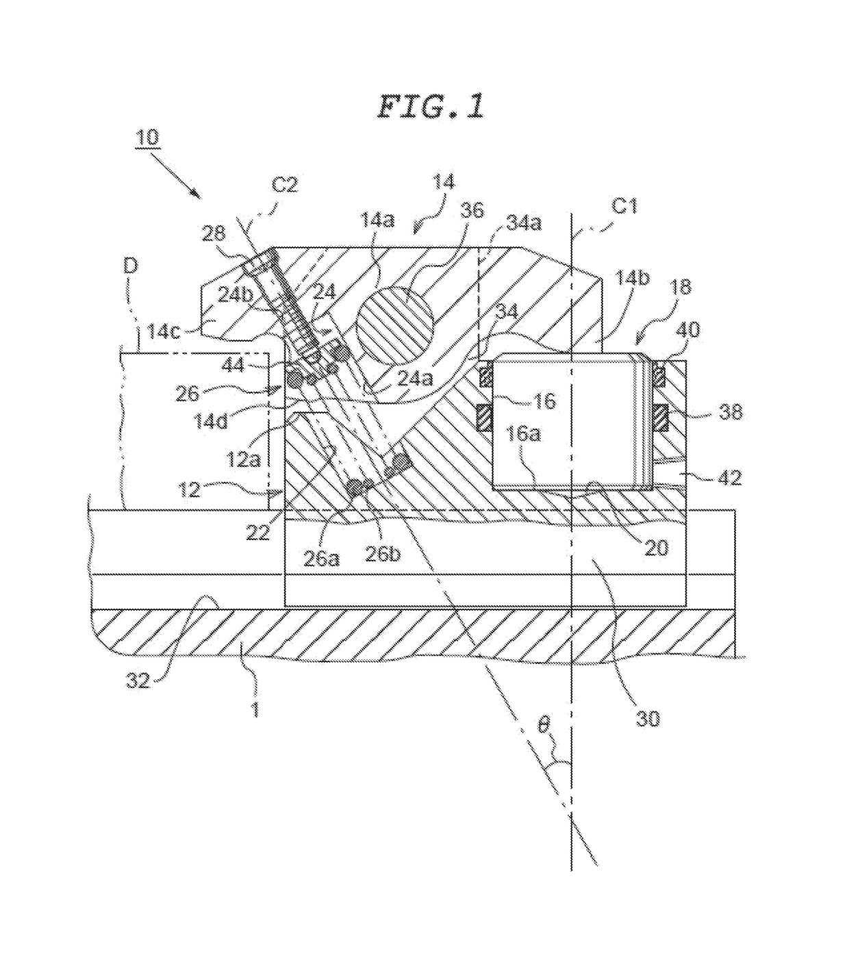
[0025]Hereinafter, an embodiment of the present invention will be described with reference to FIGS. 1 to 5. First, the structure of a clamp device 10 will be described with reference to FIGS. 1 to 4 showing a release state prior to fixing an object to be fixed.

[0026]The clamp device 10 according to the present invention is mounted on a support stand 1 such as a table when being used. A T-leg 30 is formed at a lower portion of a housing 12 and fitted into a T-groove 32 formed in the support stand 1, so as to be movable in a horizontal direction (a right-left direction in FIG. 1).

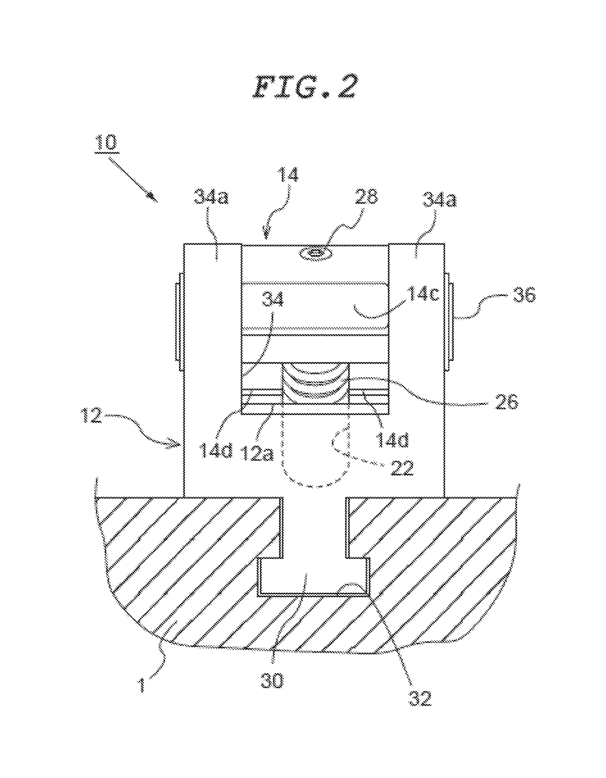
[0027]At the left end side (leading end side) of the housing 12 in FIG. 1, a pair of right and left side walls 34a are provided in a standing manner as shown in FIG. 2. A groove 34 having a U shape in a side view is formed between the side walls 34a. A pivotal support shaft 36 is provided to both side walls 34a and at a middle portion of the housing 12 in the right-left direction, and a fulcrum portion 14a pr...


PUM


Abstract

An output part is provided to the left end of a clamp arm that is supported by a housing so as to be slidable in the vertical direction. At the left end of the housing, a first hole for spring fitting opens obliquely upward towards the output part. A through hole that links the upper surface and the lower surface of the clamp arm is disposed obliquely upward at a left-leaning part of the clamp arm. A second hole for spring fitting and a female screw hole are formed, in that order, upwards in the through hole. A return spring that is installed through the first hole and the second hole impels the output part upwards. A push bolt that is screwed into the female screw hole rom above compresses the return spring.

Description

TECHNICAL FIELD[0001]The present invention relates to a clamp device which fixes an object to be fixed such as a mold or a workpiece to a support stand such as a table, and more specifically relates to a clamp device of a type in which a middle portion of a clamp arm in a longitudinal direction thereof is swingably supported.BACKGROUND ART[0002]As such a type of conventional clamp device, there is a clamp device disclosed in Patent Literature 1 (Japanese Laid-Open Patent Publication No. H08-177814). The clamp device of the conventional art is configured as follows.[0003]A middle portion of a clamp arm in a longitudinal direction thereof is mounted on a housing (clamp arm receiving stand) via a fulcrum shaft so as to be swingable in an up-down direction. A leading end portion of the clamp arm is provided with an output portion (working point) which presses an object to be fixed, and a rear end portion of the clamp arm is provided with an input portion (power point) which is pressed u...

Claims


Application Information

Patent Timeline
IPC IPC(8): B25G3/18F16B21/00F16D1/00B23Q3/08B25B5/06B23Q3/06
CPCB23Q3/082B25B5/064B23Q3/06Y10T403/602
Inventor YONEZAWA, KEITARO
Owner KOSMEK LTD (JP)
Why Eureka
Try Eureka