
Method of fabricating optical ceramics containing compositionally tailored regions in three dimension

Active Publication Date: 2012-09-06
RAYTHEON CO
View PDF3 Cites 30 Cited by
  • Summary
  • Abstract
  • Description
  • Claims
  • Application Information

AI Technical Summary

Benefits of technology

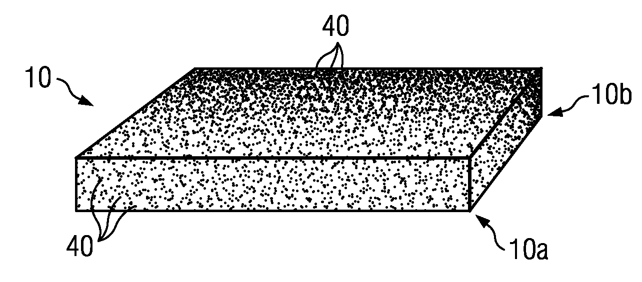
[0008]Some embodiments of the disclosure may provide one or more of the following technical advantages. A technical advantage of some embodiments may include the ability to make an optical ceramic having a desired compositional profile in all the three dimensions.
[0010]A technical advantage of some embodiments may include an optical ceramic having a compositional profile comprising a dopant gradient. In some embodiments, an optical ceramic having a compositional profile comprising a dopant gradient may have a technical advantage that may allow reducing, substantially eliminating and / or eliminating non-uniform temperatures within the optical ceramic. In some embodiments, an optical ceramic having a compositional profile comprising a dopant gradient may have a technical advantage that may allow uniform absorption of pump light. In some embodiments, an optical ceramic having a compositional profile comprising a dopant gradient may have a technical advantage that may allow uniform pump power distribution.
[0011]A technical advantage of an optical ceramic of the disclosure may include reducing beam distortion. A technical advantage of an optical ceramic of the disclosure may include reducing, minimizing or substantially eliminating thermal lensing. A technical advantage of an optical ceramic of the disclosure may include increased resistance to thermal stress fracture.
[0012]A technical advantage of methods of the disclosure to make an optical ceramic may include a higher manufacturing yield. A technical advantage of methods of the disclosure to make an optical ceramic may include reducing manufacturing costs.
[0013]Further technical advantages of particular embodiments of the present disclosure may include overall device / system performance derived from better thermal management and / or compact integrated designs.

Problems solved by technology

However, methods used to manufacture optical components are limited in their ability to control the 3D composition and / or microstructure of an optical component.
However, none of these methods have the ability to obtain desired smoothly varying compositional profiles varying spatially in all the 3D.

Method used


Image

  • Method of fabricating optical ceramics containing compositionally tailored regions in three dimension
  • Method of fabricating optical ceramics containing compositionally tailored regions in three dimension
  • Method of fabricating optical ceramics containing compositionally tailored regions in three dimension

Examples


Embodiment Construction

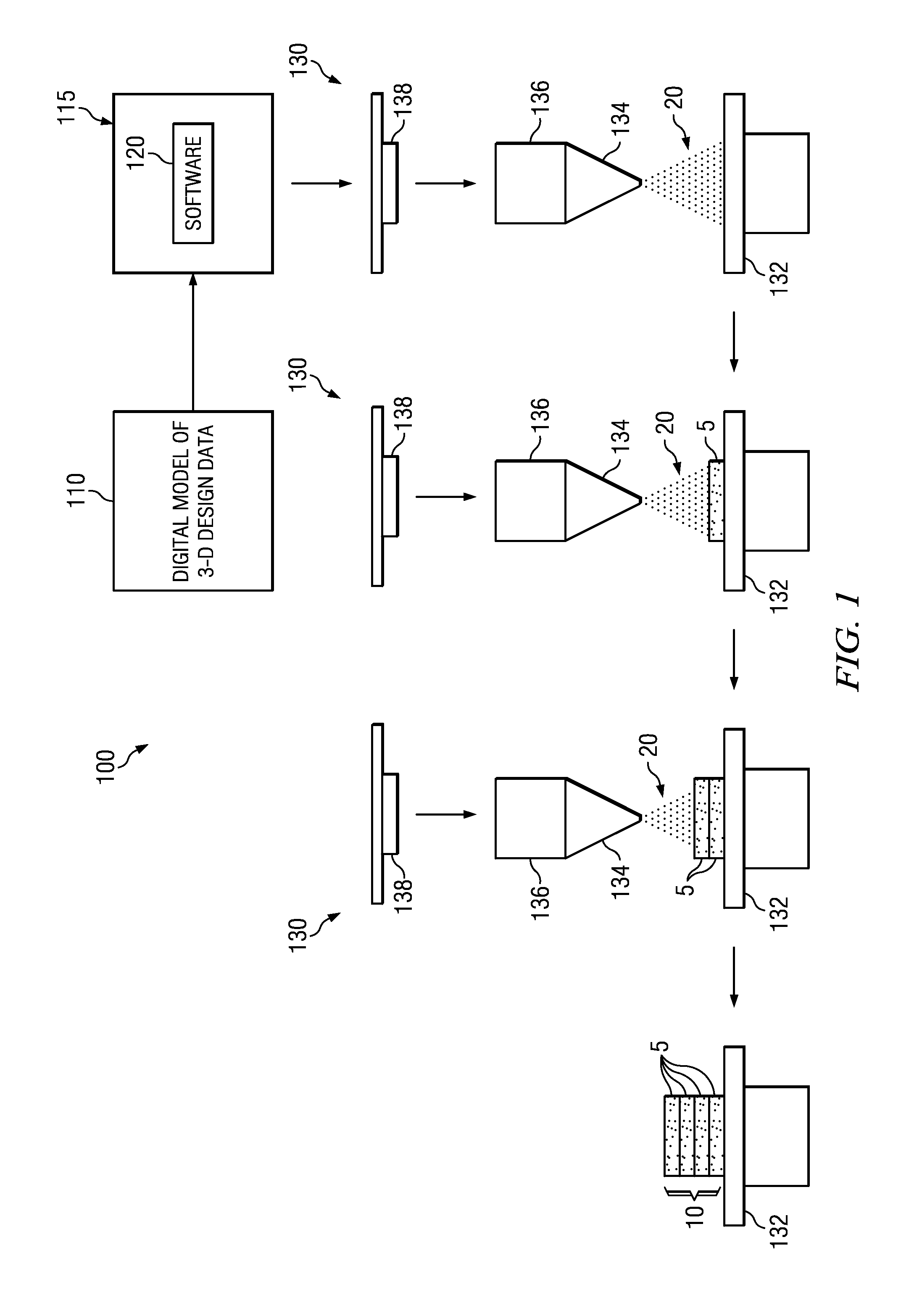
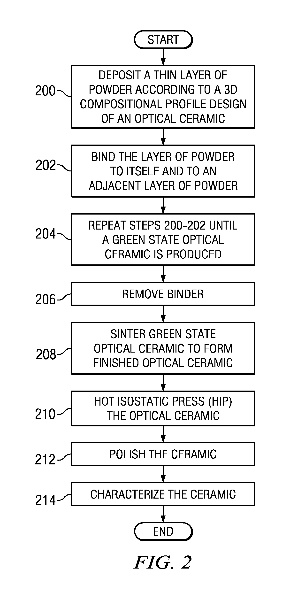
[0025]It should be understood at the outset that, although example implementations of embodiments of the disclosure are illustrated below, embodiments of the present disclosure may be implemented using any number of techniques, whether currently known or not. The present disclosure should in no way be limited to the example implementations, drawings, and techniques illustrated below. Some embodiments of the disclosure and associated advantages may be best understood by reference to FIGS. 1-4 wherein like numbers refer to same and like parts.

[0026]The present disclosure relates, in some embodiments, to methods for making optical ceramics by depositing thin layers of powder and binding the powder and layers to each other. The depositing of the powder may be done using micro-deposition techniques (e.g., electrostatic deposition or electro-photographic deposition techniques). In some instances, a 3D printer may perform one or more of these methods to accomplish the depositing and bindin...


PUM

PropertyMeasurementUnit
Compositionaaaaaaaaaa
Concentrationaaaaaaaaaa
Levelaaaaaaaaaa

Abstract

In accordance with the present embodiment, a method for making an optical ceramic comprises depositing a plurality of thin layers of powder. The powder comprises a first optical material powder having a first dopant level, and a second optical material powder. The first and second optical material powders are deposited for each layer based on the first dopant level and according to data associated with a three-dimensional (3D) compositional profile design of an optical ceramic. The method further comprises binding the first and second optical material powders of each thin layer to each other and each thin layer with an adjacent layer such that a green state optical ceramic is produced based on the 3D compositional profile design. The method further comprises densifying the green state optical ceramic to obtain the optical ceramic.

Description

FIELD OF THE DISCLOSURE[0001]The present disclosure relates, in some embodiments, to methods for making optical ceramics (e.g., solid state laser gain media) using material or micro-material deposition methods. The disclosure also relates to compositions comprising optical ceramics having three dimensionally tailored compositional profiles (e.g., compositional gradient profiles and / or compositional segmented profiles).BACKGROUND OF THE DISCLOSURE[0002]Optical components have a wide variety of applications and may be used in various laser systems, in medical imaging devices, in gradient index (GRIN) optics, scintillators, and other optical devices. These applications depend on the ability of an optical component to transmit and emit light which relies in part on the microstructure and composition of the optical component. However, methods used to manufacture optical components are limited in their ability to control the 3D composition and / or microstructure of an optical component. Op...

Claims


Application Information

Patent Timeline
IPC IPC(8): G02B1/00C04B35/00
CPCB29D11/00G02B1/02C04B35/44C04B35/505C04B35/553C04B35/6455C04B2235/3203C04B2235/3213C04B2235/3224C04B2235/3225C04B2235/3232C04B2235/3241C04B2235/6026C04B2235/75C04B2235/762C04B35/115
Inventor IMHOLT, JIYUN C.GENTILMAN, RICHARD L.HARTNETT, THOMAS M.
Owner RAYTHEON CO
Learn More