Eureka AIR delivers breakthrough ideas for toughest innovation challenges, trusted by R&D personnel around the world.

Illumination system and projection device comprising the same

a technology of projection device and projection system, which is applied in the direction of lighting and heating apparatus, instruments, optical elements, etc., can solve the problems of waste of light energy and low luminous efficiency of projection device, and achieve the effect of improving luminous efficiency

Inactive Publication Date: 2012-08-30
DELTA ELECTRONICS INC
View PDF2 Cites 16 Cited by
  • Summary
  • Abstract
  • Description
  • Claims
  • Application Information

AI Technical Summary

Benefits of technology

[0010]An objective of the present invention is to provide an illumination system, which can be applied to a projection device to achieve miniaturization of the projection device and improve the luminous efficiency.
[0012]According to the above descriptions, the illumination system of the present invention allows for optimized use of the light source to increase the luminance of images displayed by the projection device using the illumination system of the present invention, and can also reduce non-uniformity in the color of the images. Meanwhile, the projection device that uses the illumination system of the present invention can also prevent the overuse of energy sources, and have a decreased volume of the projection devices since it does not require complicated illumination components.

Problems solved by technology

However, such a projection device has too low of a luminous efficiency and wastes a large amount of light energy.

Method used


Image

  • Illumination system and projection device comprising the same
  • Illumination system and projection device comprising the same
  • Illumination system and projection device comprising the same

Examples


Embodiment Construction

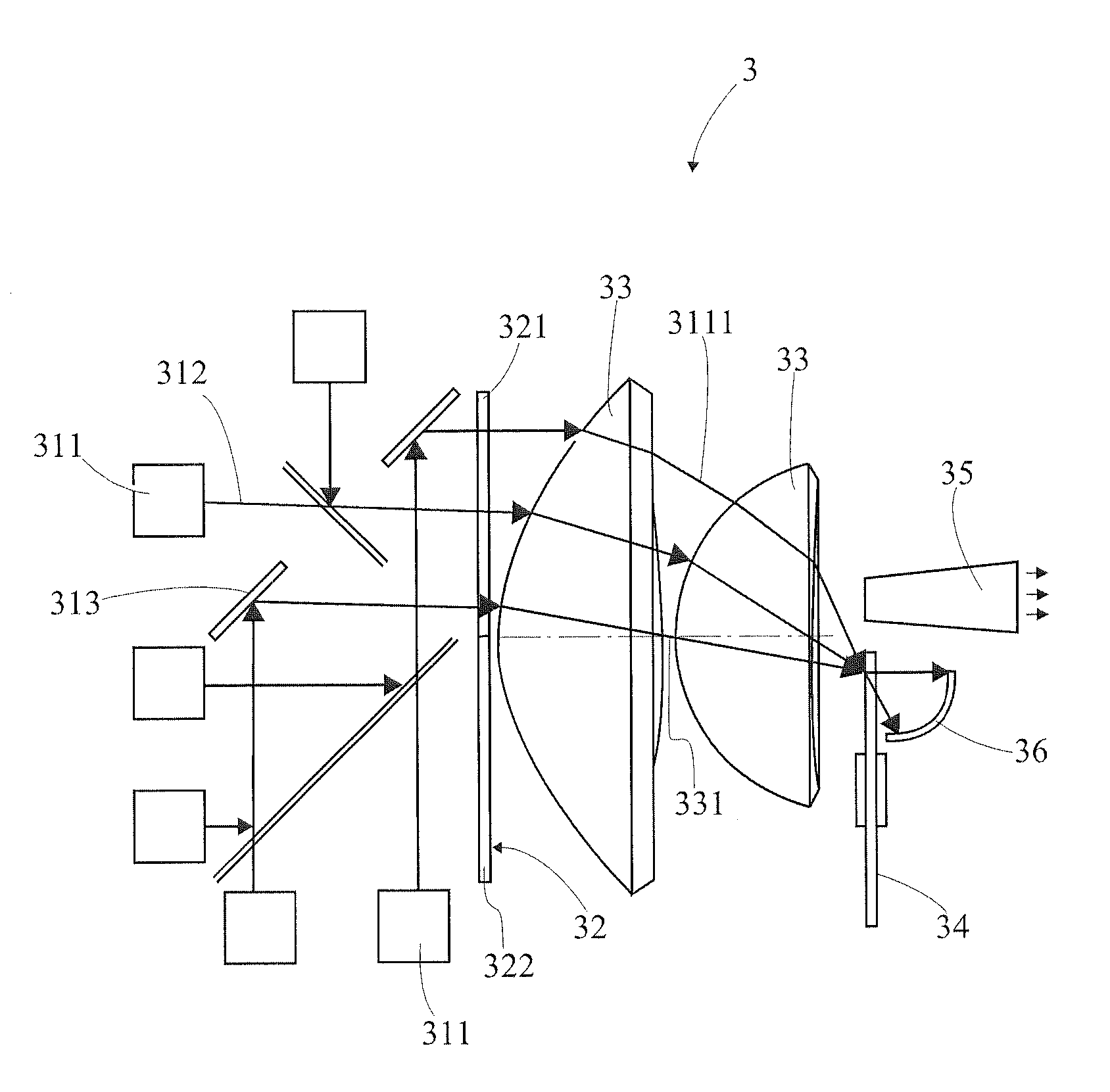
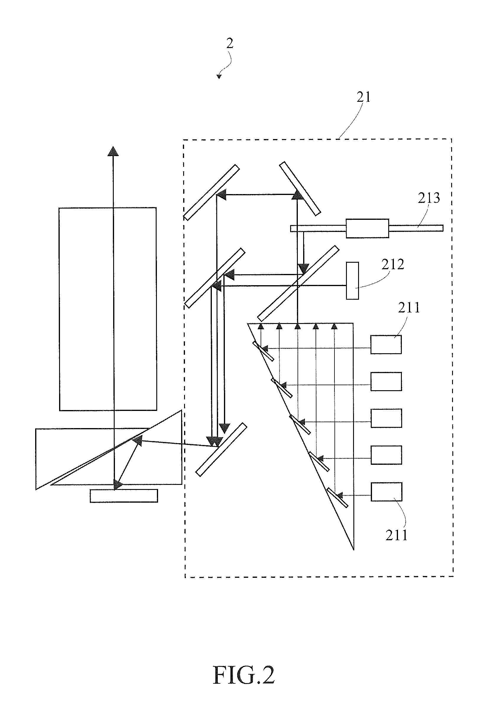
[0021]In the following descriptions, the present invention will be explained with reference to embodiments thereof. The present invention relates to an illumination system and a projection device using the illumination system. The projection device may be a device with projection and display functions such as a digital light processing (DLP) projection display or a liquid crystal display (LCD) projection display. It shall be appreciated that in the following embodiments and the attached drawings, the description of the embodiments is only for the purpose of illustration rather than limitation. Meanwhile, in the following embodiments and attached drawings, elements not directly related to the present invention are omitted from depiction; and dimensional relationships among individual elements in the attached drawings are illustrated only for ease of understanding but not to limit the actual scale.

[0022]The first embodiment of the present invention is an illumination system 3 for use ...


PUM


Abstract

An illumination system and a projection device comprising the same are provided. The projection device comprises an imaging system and the illumination system. The illumination system comprises a first light source, a dichroic element, at least one condensing element, a rotary wheel and a light integrating element. The first light source provides a first wave band light, and the rotary wheel has at least one wave band transforming area and a reflecting area. After passing through the dichroic element and the at least one condensing element, the first wave band light will be focused onto the at least one wave band transforming area to be transformed into a second wave band light or be focused onto the reflecting area that will be reflected. The second wave band light and the reflected first wave band light will be focused on the light integrating element by the at least one condensing element.

Description

[0001]This application claims priority to Taiwan Patent Application No. 100106331 filed on Feb. 25, 2011, the disclosures of which are incorporated by reference herein in their entirety.CROSS-REFERENCES TO RELATED APPLICATIONS[0002]Not applicable.BACKGROUND OF THE INVENTION[0003]1. Field of the Invention[0004]The present invention relates to an illumination system and a projection device comprising the illumination system. More particularly, the present invention relates to an illumination system that performs wavelength transformation on a particular wave band light and a projection device using the illumination system.[0005]2. Descriptions of the Related Art[0006]Over recent years, with the continuous advancement of technologies for manufacturing projection devices, lightweight and slim projection devices have become the mainstream product in the market. The demands of new and improved products in the market have led to the continuous improvement of the design of projection device...

Claims


Application Information

Patent Timeline
IPC IPC(8): F21V9/16G03B21/14
CPCG03B21/2013F21S10/007G03B33/12H04N9/3114H04N9/3152H04N9/3164F21V13/14G03B21/2066G03B21/28G03B21/2033G02B26/0833F21S10/005H04N9/315H04N9/3197G02B26/008G03B21/204
Inventor HUANG, JUNE-JEI
Owner DELTA ELECTRONICS INC
Why Eureka
Eureka Blog
Learn More