
Method and system for automatically preventing deadlock in multi-robot systems

a multi-robot system and deadlock technology, applied in the direction of electric programme control, programme-controlled manipulators, programme control, etc., can solve the problems of unfavorable robots and work pieces being handled, unfavorable robots and work pieces, and possible interference between objects, so as to avoid at least one deadlock condition and prevent the plurality of deadlocks

Active Publication Date: 2012-08-23
FANUC ROBOTICS NORTH AMERICA
View PDF3 Cites 55 Cited by
  • Summary
  • Abstract
  • Description
  • Claims
  • Application Information

AI Technical Summary

Benefits of technology

[0017]In one embodiment, a method for preventing deadlock of a pair of robots which have a common workspace, each of the robots being controlled by an associated program wherein when the programs are executed concurrently each of the robots occupies at least a portion of the common workspace during a portion of execution of the associated program, said method comprising the steps of: during concurrent execution of the programs identifying portions of the common workspace occupied by the robots; identifying at least one interference region wherein the portions of the common workspace overlap; analyzing the at least one interference region and identifying where at least one deadlock condition of the two robots can occur; and avoiding the at least one deadlock condition during execution of the programs by automatically determining and executing at least one deadlock-free motion statement prior to execution of any motion of the robots that results in the at least one deadlock condition.
[0019]In another embodiment, a method for preventing deadlock of a plurality of robots which have a common workspace, each of the robots being controlled by an associated program wherein when the programs are executed concurrently each of the robots occupies at least a portion of the common workspace during a portion of execution of the associated program, said method comprising the steps of: during concurrent execution of the programs identifying portions of the common workspace occupied by the robots; identifying at least one interference region wherein the portions of the common workspace overlap for at least two of the robots; analyzing the at least one interference region and identifying where at least one deadlock condition of the at least two robots can occur; and avoiding the at least one deadlock condition during execution of the programs by automatically determining and executing at least one deadlock-free motion statement prior to execution of any motion of the at least two robots that results in the at least one deadlock condition.
[0020]The system and method according to the invention does not require a previously known deadlock-free sequence. This system and method will automatically determine the potential deadlock conditions and identify a way to avoid these conditions. This system and method does not require priority values to prevent deadlock. This system and method prevents interference conditions and at the same time prevents the possibility of deadlock conditions to exist.

Problems solved by technology

However, when multiple objects are being moved, a potential for interference between the objects exists.
An interference exists if the at least two objects share the same space at the same time, such as when the objects have the same coordinates with respect to a common frame of reference.
As modern industrial robots move at considerable velocities, interferences between robots can result in a collision and undesirable damage to the robots and work pieces being handled by the robots.
The collisions may lead to costly down time in the manufacturing process.
For multiple robots, it is difficult to directly or effectively prevent the collision or interference thereof.
Further, it is difficult to specify an interference space in respect of a static coordinate system for multiple moving robots.
Difficulty also exists in attempting to handle a deadlock situation when two or more robots request to move to a common space at the same time.
This process is also called a “wait and move” process, which generally increases working cycle time.
However, it is difficult to effectively specify an interference space in terms of a fixed coordinate system, because the interference space is not only the function of the robot motion path but also the motion speed.
When more than one robot requests to move to a common space at the same time, it creates a deadlock situation where none of the robots can move because they are waiting for one another.
Because these systems do not determine the accumulated space occupied by the robot over time, these systems must perform comparison frequently during the robot motion.
This comparison is very expensive computationally and the cost grows exponentially as the number of robots and elements used to model a robot and tooling is increased.
These systems become more difficult when the robots reside on different controllers because they require large amounts of information to be communicated real-time between controllers.
However, the dynamic space check system generally protects a TCP only against a user-defined rectilinear space.
The method provides a two dimensional x-y projection and one dimensional height for collision detection, but does not allow for three-dimensional, real time collision detection.
The robot is also modeled by spheres only, thereby resulting in insufficient protection of critical process paths of the robots.
Deadlock conditions occur when the programs or tasks are in such a state that continued sequential execution of any of the programs or tasks will result in interference between one or more robots associated with the programs or tasks and that there is no program or task that can proceed in the sequential manner without interference.
While this method can avoid deadlock, it provides no capability of allowing operation if the set deadlock-free order has not been determined.
Furthermore, it does not allow operation that may be deadlock-free if the requested order is outside the prescribed deadlock-free order.

Method used


Image

  • Method and system for automatically preventing deadlock in multi-robot systems
  • Method and system for automatically preventing deadlock in multi-robot systems
  • Method and system for automatically preventing deadlock in multi-robot systems

Examples


Embodiment Construction

[0034]The following description is merely exemplary in nature and is not intended to limit the present disclosure, application, or uses. It should be understood that throughout the drawings, corresponding reference numerals also indicate like or corresponding parts and features. In respect of the methods disclosed, the steps presented are exemplary in nature, and thus, are not necessary or critical.

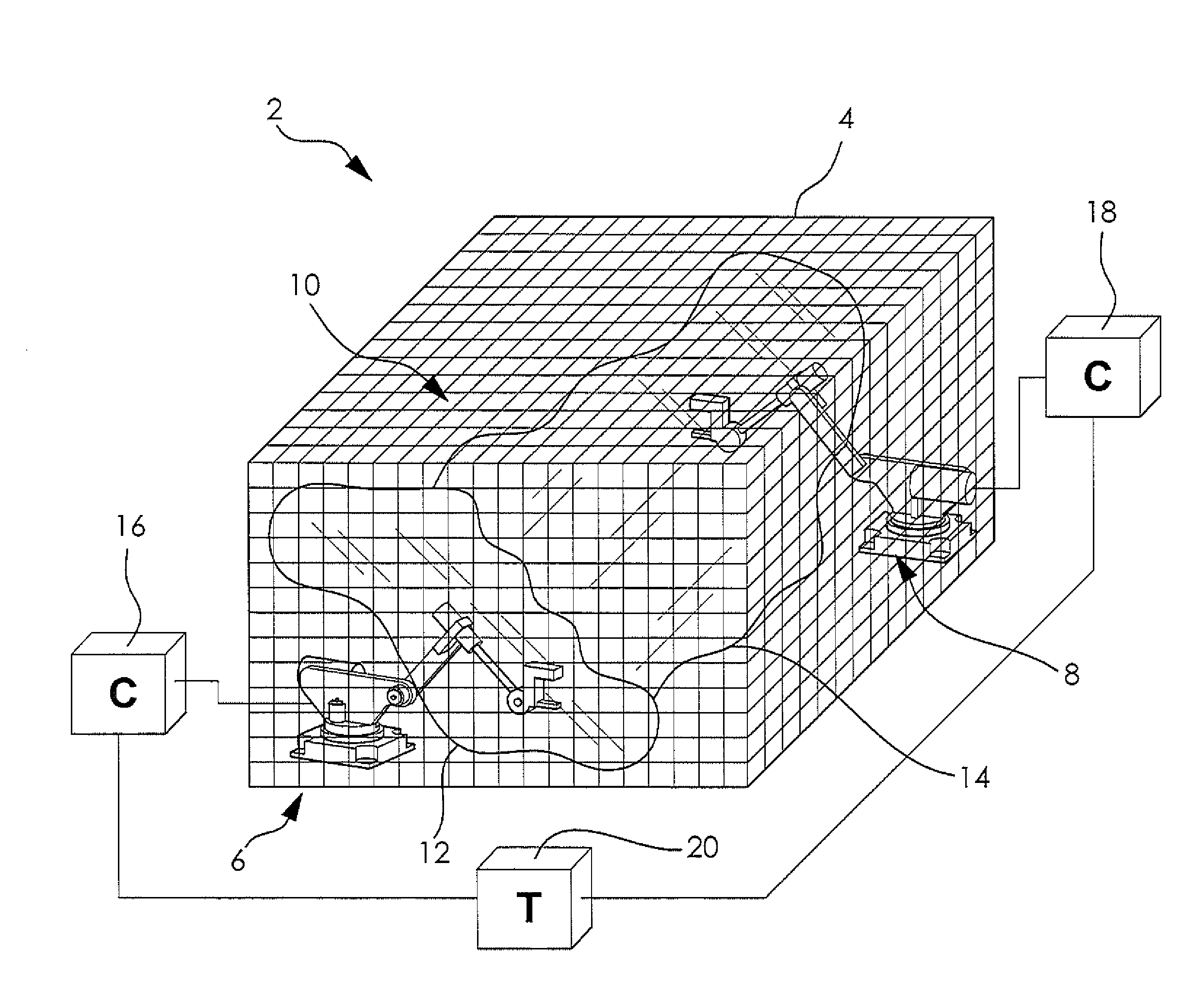
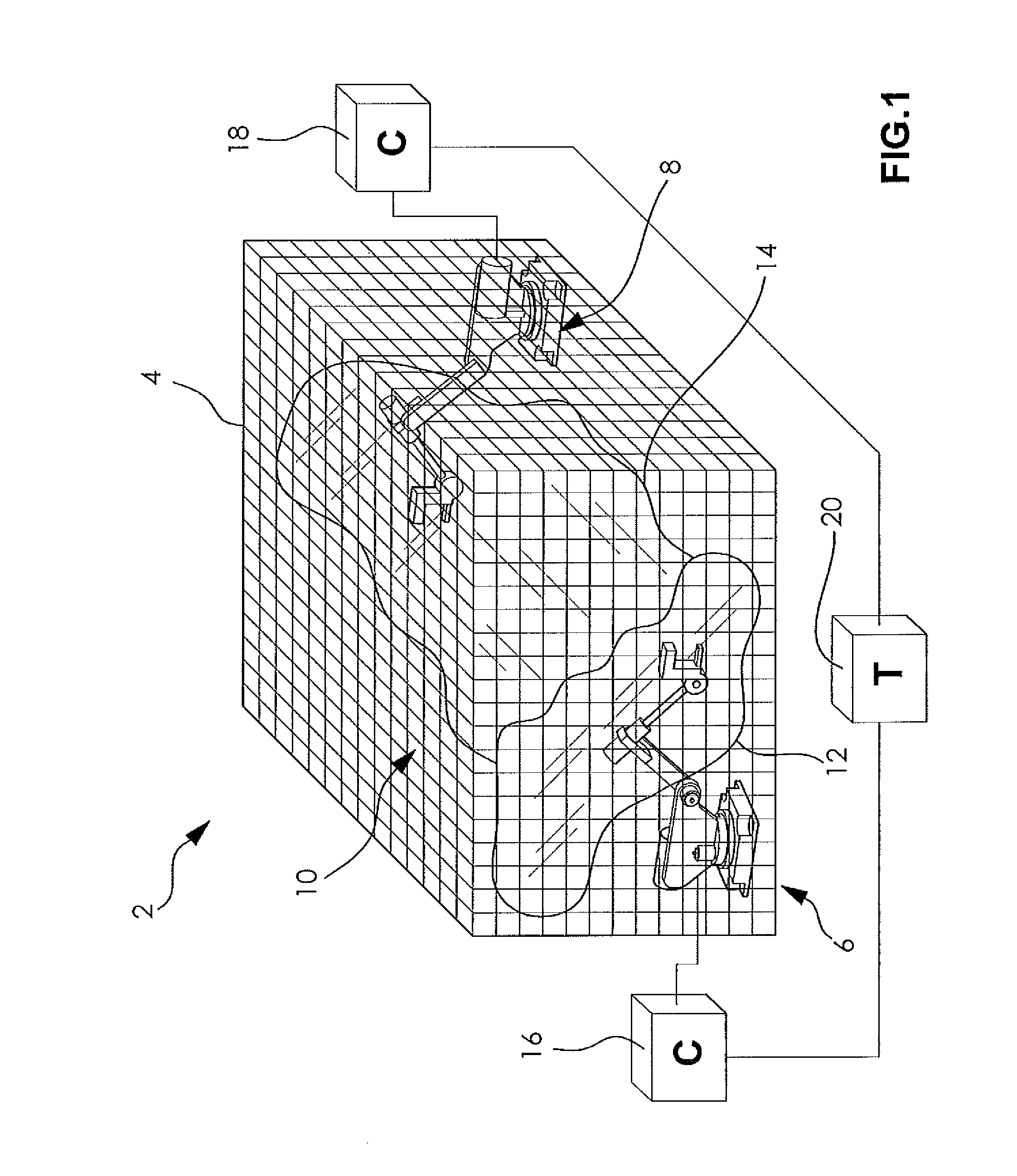
[0035]FIG. 1 is a schematic diagram showing a robotic system 2 for controlling collision avoidance between multiple robots. As nonlimiting examples, the robotic system 2 may be one of a body shop robot system, a waterjet cutting robot system, a laser welding robot system, an arc welding robot system, and a paint robot system having at least two robots. Other robotic systems 2 having a plurality of robots may also be employed, as desired.

[0036]The robotic system 2 includes a work cell 4 defining an envelope within which a first robot 6 and a second robot 8 are configured to operate. The fi...


PUM


Abstract

A system and method for controlling avoiding collisions and deadlocks in a workcell containing multiple robots automatically determines the potential deadlock conditions and identifies a way to avoid these conditions. Deadlock conditions are eliminated by determining the deadlock-free motion statements prior to execution of the motions that have potential deadlock conditions. This determination of deadlock-free motion statements can be done offline, outside normal execution, or it can be done during normal production execution. If there is sufficient CPU processing time available, the determination during normal production execution provides the most flexibility to respond to dynamic conditions such as changes in I / O timing or the timing of external events or sequences. For minimal CPU impact the determination is done offline where many permutations of programming sequences can be analyzed and an optimized sequence of execution may be found.

Description

CROSS-REFERENCE TO RELATED APPLICATION[0001]This application is a continuation-in-part of the co-pending U.S. patent application Ser. No. 12 / 124,430 filed May 21, 2008.[0002]This application claims the benefit of U.S. provisional patent application Ser. No. 61 / 482,808 filed May 5, 2011.FIELD OF THE INVENTION[0003]The present invention relates generally to a system for controlling a plurality of robots and a method for controlling motion interference avoidance for the plurality of robots.BACKGROUND OF THE INVENTION[0004]Movement of objects in space is a necessary task in a typical manufacturing environment. Robotics have increasingly been employed to effect the necessary movement. However, when multiple objects are being moved, a potential for interference between the objects exists. An interference exists if the at least two objects share the same space at the same time, such as when the objects have the same coordinates with respect to a common frame of reference.[0005]As modern in...

Claims


Application Information

Patent Timeline
Patent Type & Authority Applications(United States)
IPC IPC(8): G05B19/418
CPCB25J9/1666B25J9/1676G05B2219/40492G05B2219/40442G05B2219/40477G05B2219/39135
Inventor MCGEE, H. DEANCHANG, TIEN L.SWANSON, PETERTAO, JIANMINGXIAO, DIWONG, HO CHEUNGCHENG, SAI-KAITSAI, JASON
Owner FANUC ROBOTICS NORTH AMERICA
Learn More