Optical pickup device and optical disc apparatus
a pickup device and optical disc technology, applied in the field of optical pickup devices and optical disc devices, can solve the problems of increasing cost, unavoidable disposal of four detectors, and complicated optical systems of optical pickup devices, and achieve the effect of increasing the s/n ratio and reducing the number of components of an optical system
- Summary
- Abstract
- Description
- Claims
- Application Information
AI Technical Summary
Benefits of technology
Problems solved by technology
Method used
Image


Examples
embodiment 1
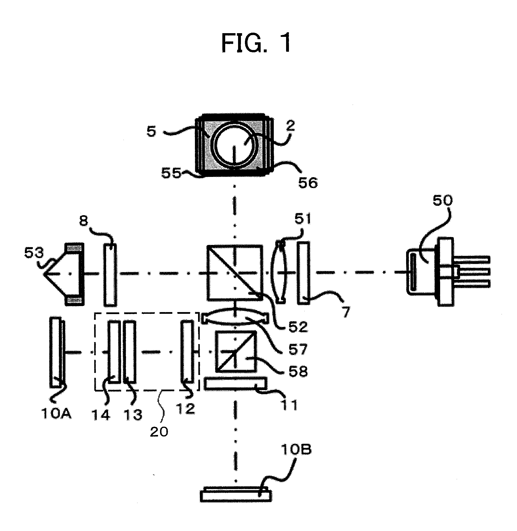
[0031]FIG. 1 is a diagram illustrating an optical system of an optical pickup device according to an embodiment 1 of the present invention. Although the embodiment 1 aims to reproduce data stored in a BD multi-layer disc, an optical disc other than the above or a single-layer disc may be used.
[0032]A light beam of about 405 nm in wavelength is emitted from a laser diode 50 as divergent light. The emitted light beam passes through a half wave plate 7, is converted into an almost collimated light beam by a collimator lens 51 and is incident on a polarized beam splitter 52. The polarized beam splitter 52 is a light splitting element having a function of reflecting almost 100% of s-polarized light and transmitting almost 100% of p-polarized light.
[0033]A light beam of s-polarized light reflected by the polarized beam splitter 52 is reflected by a reflection mirror 55, is incident on a quarter wave plate 56 and is converted into circularly polarized light. Then, a light beam of the circu...
embodiment 2
[0065]Although the reproduction signal is obtained by separating one light beam including signal light and reference light into four light beams in the optical system according to the embodiment 1, an embodiment 2 is configured such that one light beam is separated into six light beams to generate a reproduction signal. Therefore, the embodiment 2 is different from the embodiment 1 in optical characteristics of the phase difference forming unit 20 (the grating 12, the divided wave plate 13 and the polarization grating 14) and arrangement of light receiving parts on the detector 10A.
[0066]In the embodiment 2, a light beam reflected by the polarized beam splitter 58 is separated into three light beams by the grating 12. The three light beams transmit through three regions of the divided wave plate 13 and are separated into six light beams by the polarization grating 14. The six light beams are respectively detected by six light receiving parts disposed on the detector 10A and a reprod...
embodiment 3
[0077]In the optical system according to an embodiment 3, a reproduction signal is generated by separating a light beam including signal light and reference light into six light beams. The embodiment 3 is different from the embodiment 2 in optical characteristics of the phase different forming unit 20 (including the grating 12, the divided wave plate 13 and the polarization grating 14) and arrangement of light receiving parts on the detector 10A.
[0078]In the embodiment 3, a light beam reflected by the polarized beam splitter 58 is separated into two light beams by the grating 12. The two light beams transmit through two regions of the divided wave plate 13 and are separated into six light beams by the polarization grating 14. The six light beams are respectively detected by six light receiving parts disposed on the detector 10A and a reproduction signal is generated on the basis of detection signals from the six light receiving parts.
[0079]FIG. 10A to FIG. 10C are diagrams illustrat...
PUM
 Abstract
Description
Claims
Application Information
 - R&D
- Intellectual Property
- Life Sciences
- Materials
- Tech Scout
- Unparalleled Data Quality
- Higher Quality Content
- 60% Fewer Hallucinations
Browse by: Latest US Patents, China's latest patents, Technical Efficacy Thesaurus, Application Domain, Technology Topic, Popular Technical Reports.
© 2025 PatSnap. All rights reserved.Legal|Privacy policy|Modern Slavery Act Transparency Statement|Sitemap|About US| Contact US: help@patsnap.com