
Hydrogen storage apparatus

Inactive Publication Date: 2012-08-23
NAT CENT UNIV
View PDF12 Cites 10 Cited by
  • Summary
  • Abstract
  • Description
  • Claims
  • Application Information

AI Technical Summary

Benefits of technology

[0010]In view of the foregoing, an objective of the invention is to provide a hydrogen storage apparatus capable of making the hydrogen storage material be evenly distributed and preventing the hydrogen storage material from accumulation.
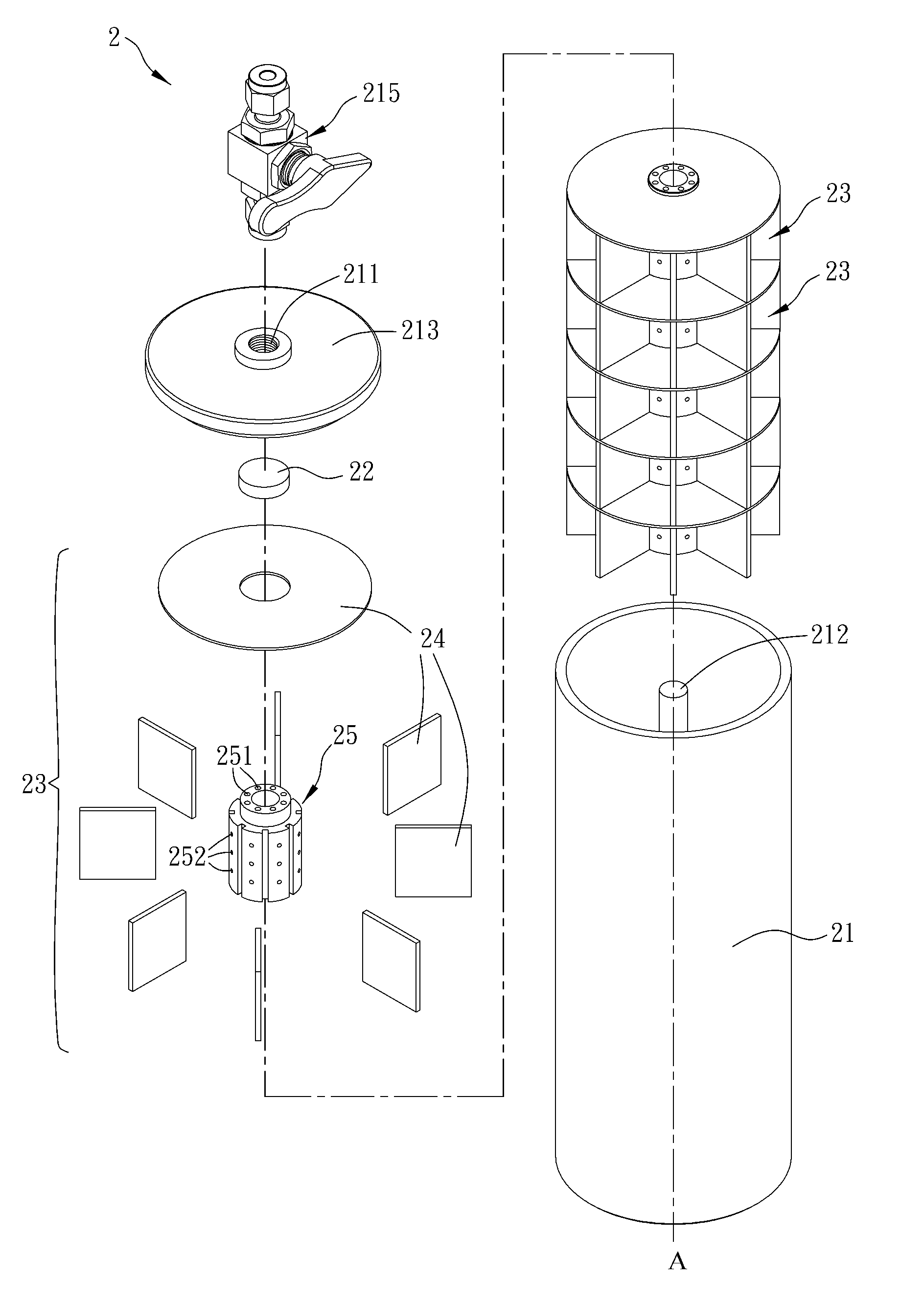
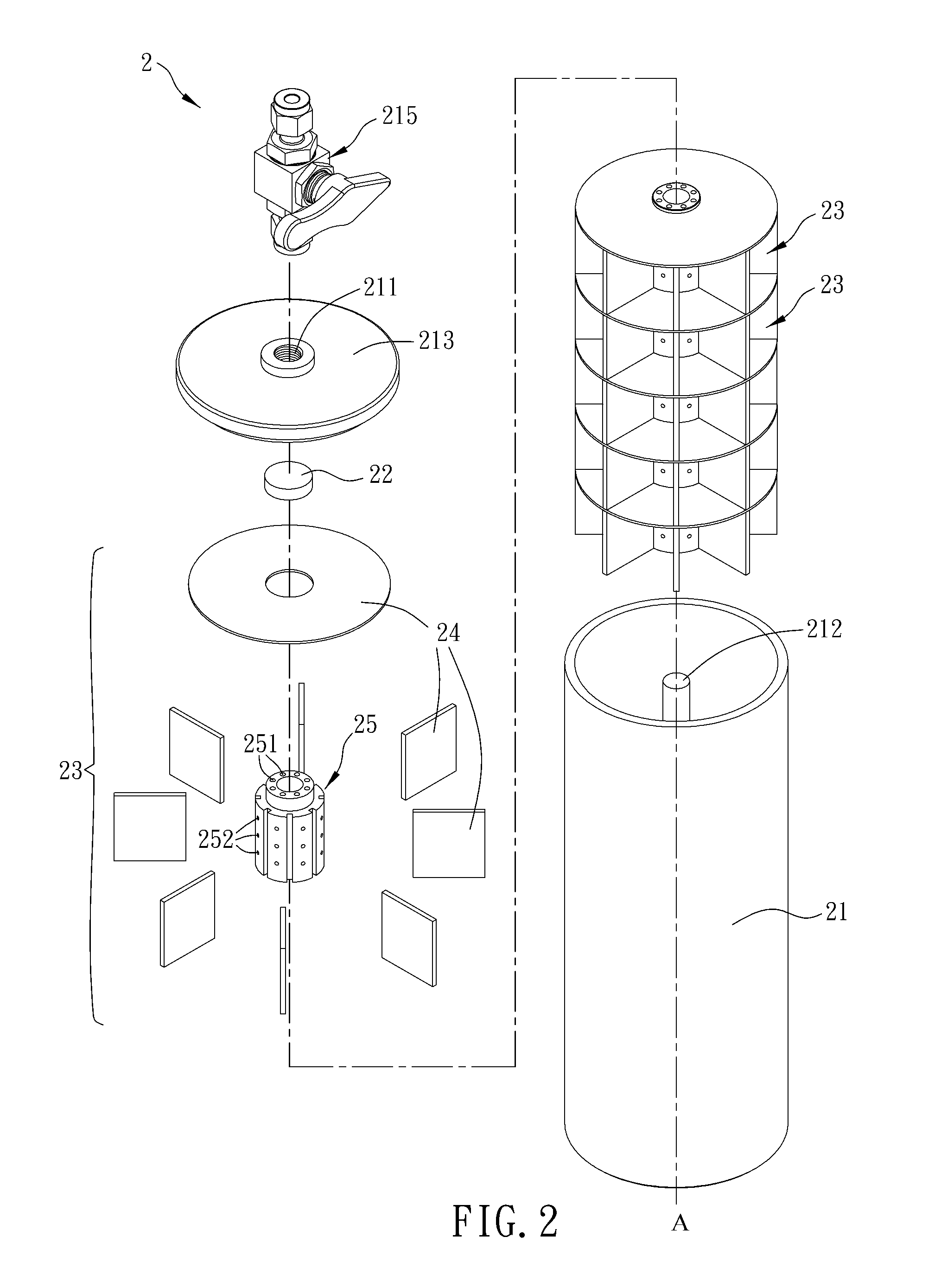
[0022]As mentioned above, the hydrogen storage apparatus according to the invention provides independent axial and radial gas flowing channels through the hydrogen channel element of the hydrogen storage unit, and utilizes the compartment structure to divide the space inside the canister into many small compartments for accommodating the hydrogen storage material, so that the hydrogen storage apparatus of the invention can ease the phenomenon that the hydrogen storage material is accumulated. In this embodiment, the stack of the hydrogen storage units is advantageous to the adjustment of the capacity of the hydrogen storage apparatus according to the actual product requirement. Compared with the prior art, the hydrogen can be smoothly delivered in the canister of the hydrogen storage apparatus of the invention, and the phenomenon that the hydrogen storage material is accumulated can be eased. Thus, it is possible to prevent the hydrogen storage apparatus from the dangers of deformation and crack caused by the uneven expansion of the hydrogen storage material in absorbing the hydrogen. In addition, the compartment structure with the high heat transfer rate can speed up the heat transfer inside / outside the canister, and can effectively increase the rate of the hydrogen storage apparatus for absorbing the hydrogen. On the other hand, the hydrogen storage apparatus can be easily installed and does not need the application and the control of the external device. These properties further expand the application range of the hydrogen storage apparatus.

Problems solved by technology

However, when the hydrogen is stored either in a low-temperature liquid state or a high-pressure gaseous state, a lot of energy has to be consumed to liquefy or compress the hydrogen.
Thus, the costs for these two hydrogen storage apparatuses are very high.
Thus, the filter rod 12 buried in the hydrogen storage material M tends to be blocked so that the hydrogen flow becomes difficult.
If the dimension of the filter pore is too large, the fine powder cannot be effectively filtered out.
In addition, the hydrogen storage material M, after being broken into powder, tends to be unevenly accumulated inside the canister 11 of the conventional hydrogen storage apparatus 1, thereby causing different expansion extents of the portions of the hydrogen storage material M in the process of generating the hydrogen, and causing the canister 11 or the flow tube 13 to deform or crack easily.

Method used


Image

  • Hydrogen storage apparatus
  • Hydrogen storage apparatus
  • Hydrogen storage apparatus

Examples


Embodiment Construction

[0032]The present invention will be apparent from the following detailed description, which proceeds with reference to the accompanying drawings, wherein the same references relate to the same elements.

[0033]FIG. 2 is a schematically decomposed illustration showing a hydrogen storage apparatus 2 according to a first embodiment of the invention. Referring to FIG. 2, the hydrogen storage apparatus 2 includes a canister 21, a first filter element 22 and at least one hydrogen storage unit 23. The hydrogen storage apparatus 2 may be loaded with a substance (also referred to as a hydrogen storage material) capable of absorbing or desorbing the hydrogen. The substance may be in the form of powder or colloid, and is not particularly restricted.

[0034]The canister 21 has an opening 211 and a rod 212. In this embodiment, the canister 21 is a cylindrical canister. However, the canister 21 may be one of a polyhedron, a sphere, an irregular body and a combination thereof according to the actual a...


PUM

PropertyMeasurementUnit
Lengthaaaaaaaaaa
Lengthaaaaaaaaaa

Abstract

A hydrogen storage apparatus includes a canister, a first filter element and at least one hydrogen storage unit. The canister has an opening and a rod. The first filter element is disposed in the opening. The hydrogen storage unit is accommodated in the canister. The hydrogen storage unit includes a compartment structure and a hydrogen channel element. The compartment structure divides a space inside the canister, and the hydrogen channel element is pierced by the rod and connected with the compartment structure. The hydrogen channel element includes a plurality of axial channels and a plurality of radial channels. The axial channels are connected with the opening and the radial channels. The radial channels are connected with the space inside the canister.

Description

CROSS REFERENCE TO RELATED APPLICATIONS[0001]This Non-provisional application claims priority under 35 U.S.C. §119(a) on Patent Application No(s). 100105443 filed in Taiwan, Republic of China on Feb. 18, 2011, the entire contents of which are hereby incorporated by reference.BACKGROUND OF THE INVENTION[0002]1. Field of Invention[0003]The invention relates to an air storage apparatus and, in particular, to a hydrogen storage apparatus.[0004]2. Related Art[0005]Recently, hydrogen has been widely applied to the industrial manufacturing processes, and the specifications in the fields of manufacturing, storage, transportation and application thereof have been gradually specified perfectly. The current hydrogen storage technology mainly includes the liquefied hydrogen storage, the high-pressure hydrogen storage, the metal hydride hydrogen storage, the alloy hydrogen storage, and the like. However, when the hydrogen is stored either in a low-temperature liquid state or a high-pressure gase...

Claims


Application Information

Patent Timeline
IPC IPC(8): F17C11/00
CPCY02E60/321F17C11/005Y02E60/32
Inventor CHUNG, CHIH-ANGLEE, SHENG-LONGLIN, CHIH-KUANGCHIOU, BO-YU
Owner NAT CENT UNIV
Learn More