Multi-blade centrifugal fan and air conditioner employing the same
a centrifugal fan and multi-blade technology, applied in machines/engines, liquid fuel engines, lighting and heating apparatus, etc., can solve problems such as abnormal noise (irritating noise) and achieve the effects of suppressing deviation, preventing flow reversal and flow separation near tongue portions, and suppressing secondary flow in a direction perpendicular to the main flow
- Summary
- Abstract
- Description
- Claims
- Application Information
AI Technical Summary
Benefits of technology
Problems solved by technology
Method used
Image
Examples
first embodiment
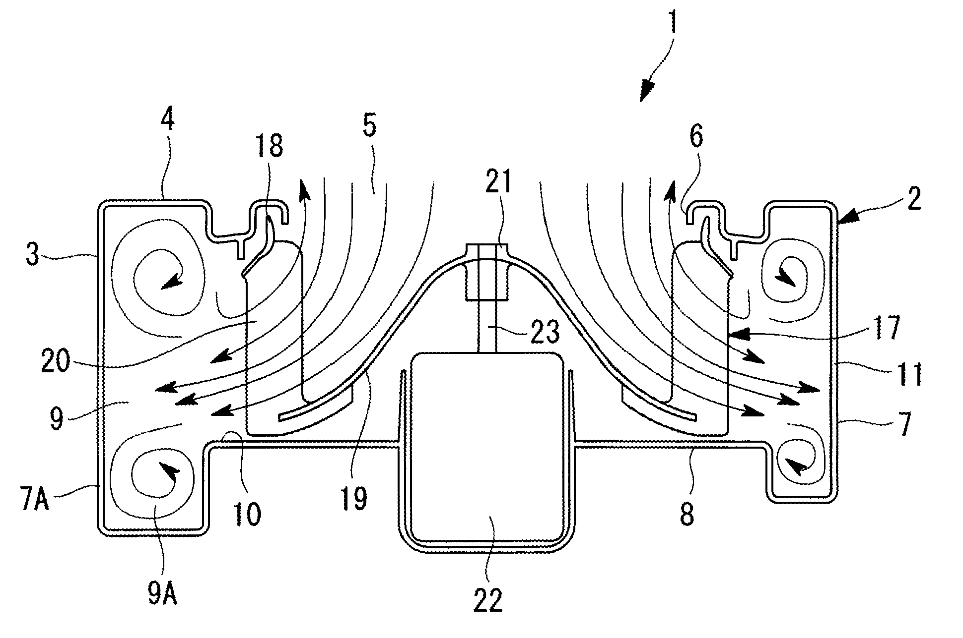
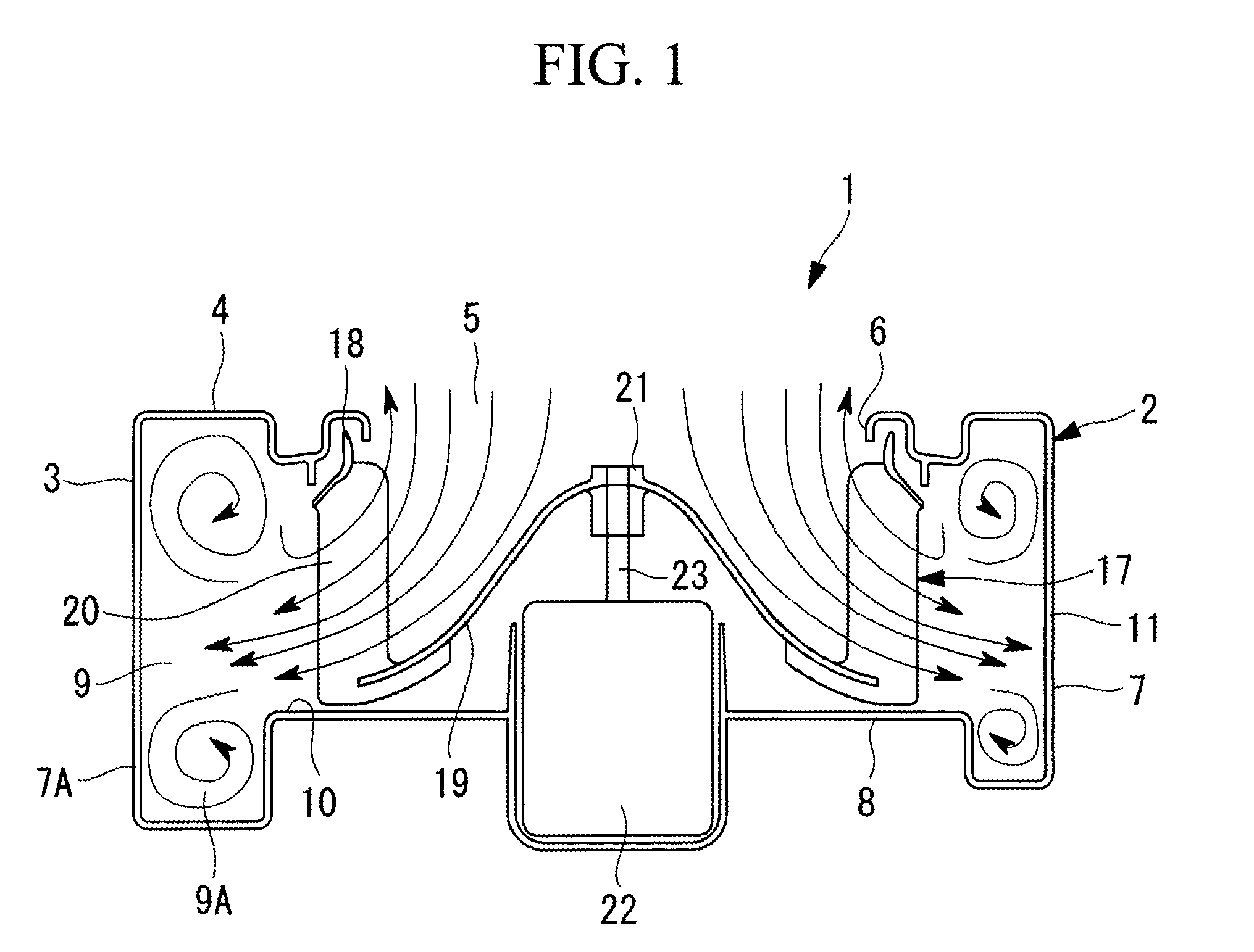
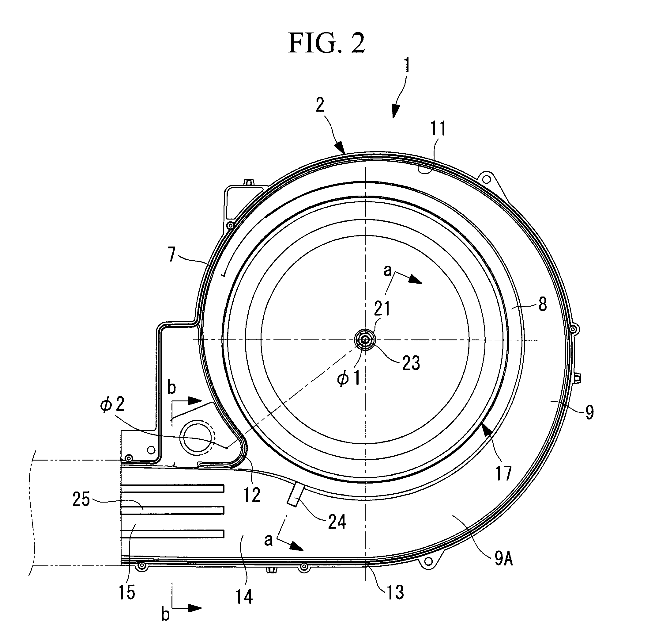
[0056]A first embodiment of the present invention will be described below by using FIGS. 1 to 4 and FIGS. 9 and 10. FIG. 1 shows a longitudinal sectional view of a multi-blade centrifugal fan according the first embodiment of the present invention, and FIG. 2 shows a lateral sectional view thereof, viewed from a lower-casing side.
[0057]A multi-blade centrifugal fan 1 is provided with a scroll casing 2 that is formed in a spiral shape (scroll shape) and is made of a plastic material.
[0058]The scroll casing 2 is formed of an upper casing 3 provided with a bell mouth 6, which forms an inlet 5 at a top surface 4, and a lower casing 7 in which an air channel 9 is formed at an outer circumference of an annular flange portion 8 that supports a motor 22 and an impeller 17. The upper casing 3 and the lower casing 7 are divided into two portions at an appropriate position in the vertical direction (rotation-axis direction), each of which is molded from a plastic material, and form the scroll ...
second embodiment
[0077]Next, a second embodiment of the present invention will be described by using FIGS. 5, 6, and 11.
[0078]The configuration of this embodiment differs from the above-described first embodiment in that a sub-blade 26 is provided instead of the protrusion 24 and the rib-like protrusions 25. Because other points are the same as those of the first embodiment, descriptions thereof will be omitted.
[0079]As shown in FIGS. 5 and 6, with the configuration of this embodiment, the sub-blade 26 that simultaneously controls a secondary flow and the occurrence of turbulence in an airflow and vortices is provided along an airflow direction at a position closer to the inner circumference than the center portion on the wall surface of the diffuser portion 15 in the region of the outlet 14, which is downstream of the spiral-end portion 13 of the scroll casing 2 provided in the axially expanded portion 7A of the lower casing.
[0080]When a center portion of the channel width at the wall surface of th...
third embodiment
[0085]Next, a third embodiment of the present invention will be described by using FIGS. 7, 8, 12, and 13.
[0086]The configuration of this embodiment differs from the above-described first embodiment in that a vortex control plate 27 and a secondary-flow control plate 29 are provided instead of the protrusion 24 and the rib-like protrusions 25. Because other points are the same as those of the first embodiment, descriptions thereof will be omitted.
[0087]As shown in FIGS. 7 and 8, in this embodiment, the vortex control plate 27, whose height in the rotation-axis direction is gradually increased over an area from upstream of the tongue portion 12 to an inner circumferential side surface in the region of the outlet 14, is provided near the tongue portion 12 in the region of the outlet 14, which is downstream of the spiral-end portion 13 of the scroll casing 2, in the axially expanded portion 7A provided in the lower casing 7. This vortex control plate 27 extends to a portion above the a...
PUM
 Abstract
Description
Claims
Application Information
 - R&D
- Intellectual Property
- Life Sciences
- Materials
- Tech Scout
- Unparalleled Data Quality
- Higher Quality Content
- 60% Fewer Hallucinations
Browse by: Latest US Patents, China's latest patents, Technical Efficacy Thesaurus, Application Domain, Technology Topic, Popular Technical Reports.
© 2025 PatSnap. All rights reserved.Legal|Privacy policy|Modern Slavery Act Transparency Statement|Sitemap|About US| Contact US: help@patsnap.com


