
Mold and production method for same, and Anti-reflection film

Active Publication Date: 2012-08-02
SHARP KK
View PDF5 Cites 9 Cited by
  • Summary
  • Abstract
  • Description
  • Claims
  • Application Information

AI Technical Summary

Benefits of technology

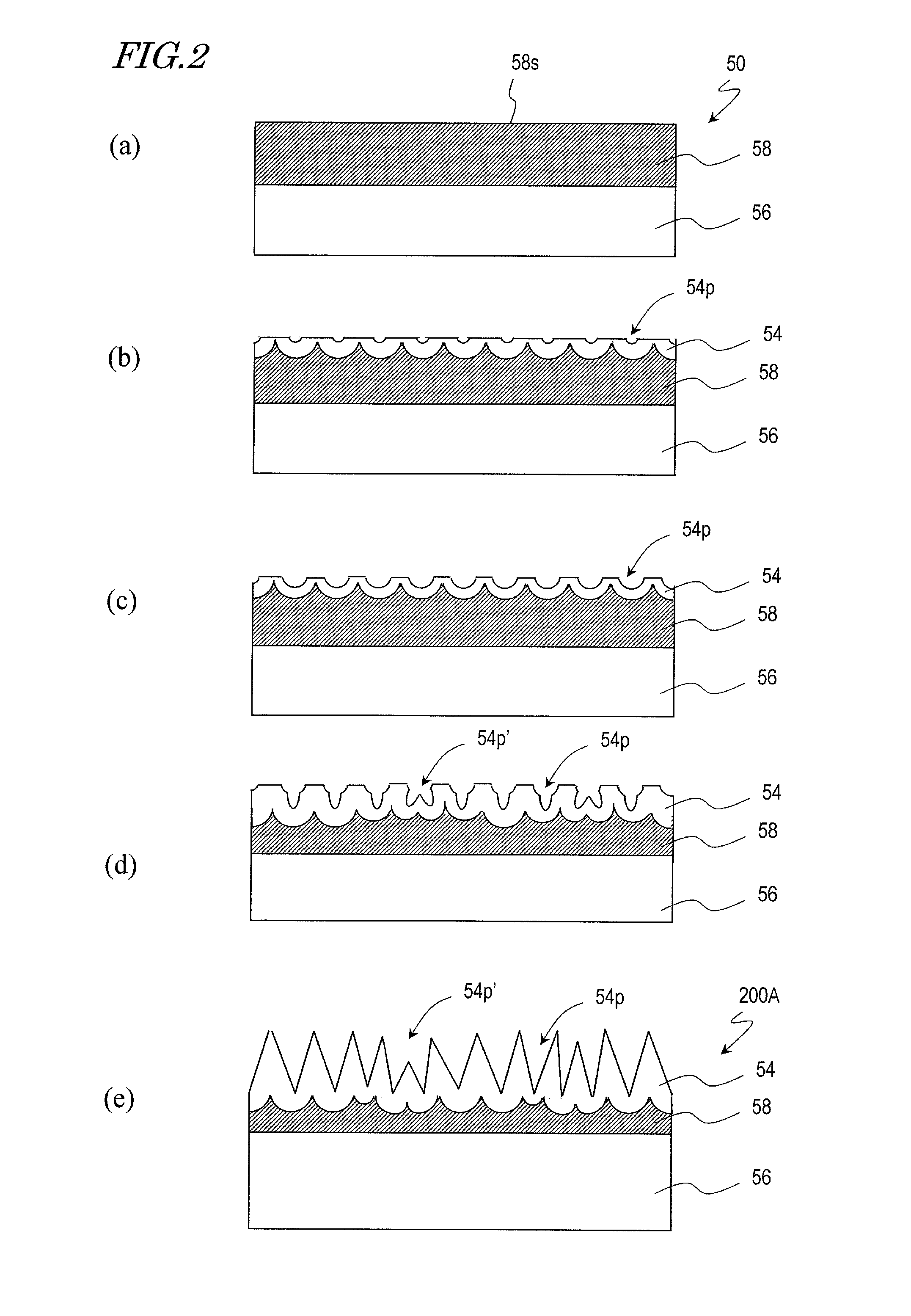
[0037]According to the present invention, a mold fabrication method is provided which is capable of preventing formation of a plurality of tiny pores in one micropore.

Problems solved by technology

This is because, when light is transmitted through the interface between media of different refractive indices, e.g., when light is incident on the interface between air and glass, the amount of transmitted light decreases due to, for example, Fresnel reflection, thus deteriorating the visibility.

Method used


Image

  • Mold and production method for same, and Anti-reflection film
  • Mold and production method for same, and Anti-reflection film
  • Mold and production method for same, and Anti-reflection film

Examples


##ventive examples 1 and 2

Inventive Examples 1 and 2, Comparative Example 1

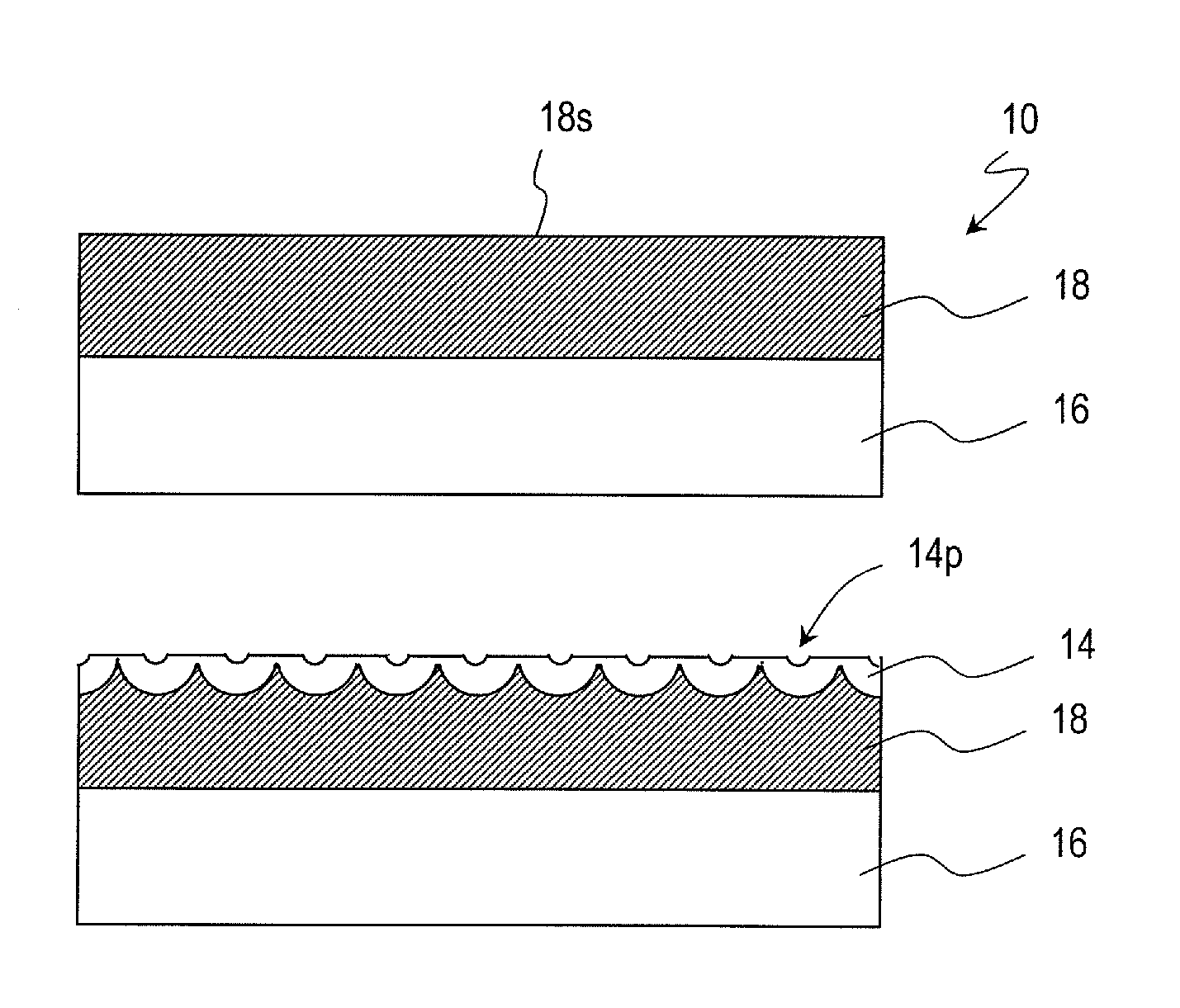
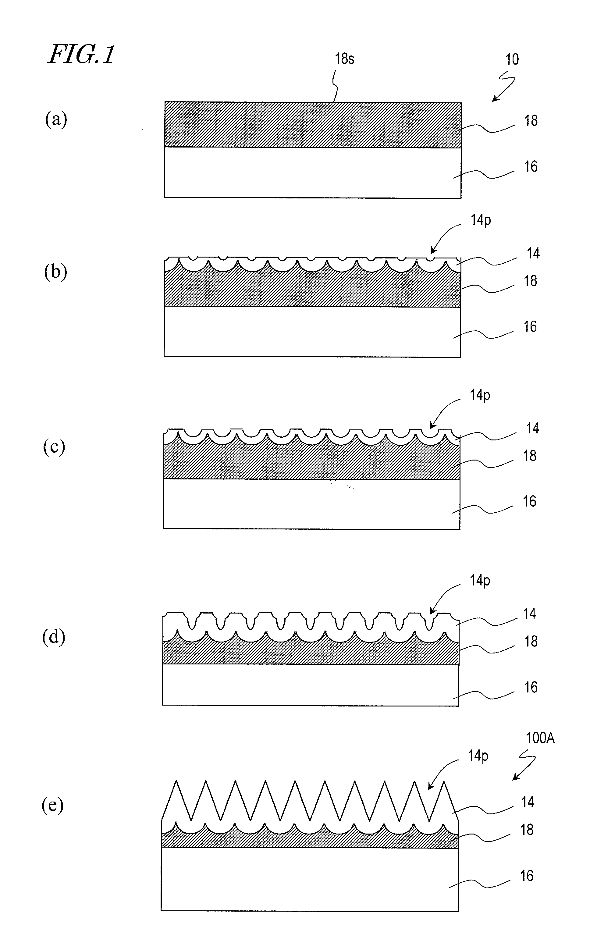
[0087]The moth-eye molds of Inventive Examples 1 and 2 have the same configuration as that of the moth-eye mold 100A shown in FIG. 1(e). The fabrication process which has previously been described with reference to FIGS. 1(a) to 1(e) was performed as described below. Note that the differences between Inventive Examples 1 and 2 were the applied voltage and the duration of the second and subsequent cycles.

[0088]The base 10 (FIG. 1(a)) used herein was prepared by forming a 1 μm thick aluminum film 18 by sputtering on a square glass substrate 16 (0.7 mm thick) of 5 cm on each side. Note that the aluminum film 18 was formed by performing 5 cycles of the step of depositing a 200 nm thick aluminum layer.

[0089]The anodization step and the etching step were alternately performed on the base 10 through 5 cycles (including 5 anodization cycles and 4 etching cycles), whereby the moth-eye mold 100A was fabricated. In each of Inventive Examples 1 a...


PUM

PropertyMeasurementUnit
Diameteraaaaaaaaaa
Diameteraaaaaaaaaa
Sizeaaaaaaaaaa

Abstract

A moth-eye mold fabrication method of an embodiment of the present invention includes the steps of: (a) anodizing a surface of an aluminum film to form a porous alumina layer which has a plurality of minute recessed portions; (b) after step (a), bringing the porous alumina layer into contact with an etching solution, thereby enlarging the plurality of minute recessed portions of the porous alumina layer; and (c) after step (b), further anodizing the surface to grow the plurality of minute recessed portions, wherein a voltage applied in step (c) is higher than a voltage applied in step (a). According to an embodiment of the present invention, a mold fabrication method is provided which is capable of preventing formation of a plurality of tiny pores in one micropore.

Description

TECHNICAL FIELD[0001]The present invention relates to a mold, a method of fabricating a mold, and an antireflection film. In this specification, the “mold” includes molds that are for use in various processing methods (stamping and casting), and is sometimes referred to as a stamper. The mold can also be used for printing (including nanoimprinting).BACKGROUND ART[0002]Display devices for use in TVs, cell phones, etc., and optical elements, such as camera lenses, etc., usually adopt an antireflection technique in order to reduce the surface reflection and increase the amount of light transmitted therethrough. This is because, when light is transmitted through the interface between media of different refractive indices, e.g., when light is incident on the interface between air and glass, the amount of transmitted light decreases due to, for example, Fresnel reflection, thus deteriorating the visibility.[0003]An antireflection technique which has been receiving attention in recent year...

Claims


Application Information

Patent Timeline
IPC IPC(8): B29C33/38B32B3/18B29C33/42C25D11/04C25D11/12C25D11/18C25D11/24G02B1/11G02B1/118
CPCC25D11/12Y10T428/24479G02B1/118C25D11/18
Inventor ISURUGI, AKINOBUMINOURA, KIYOSHIIMAOKU, TAKAO
Owner SHARP KK
Learn More