
Light guide plate, surface light source device, transmission-type image display device, method of manufacturing light guide plate, and ultraviolet curing type ink-jet ink for light guide plate

a technology of light guide plate and ultraviolet curing type, which is applied in the direction of lighting and heating apparatus, semiconductor devices for light sources, instruments, etc., can solve the problem of low luminance and achieve the effect of higher luminance and higher luminan

Inactive Publication Date: 2012-08-02
SUMITOMO CHEM CO LTD +1
View PDF13 Cites 20 Cited by
  • Summary
  • Abstract
  • Description
  • Claims
  • Application Information

AI Technical Summary

Benefits of technology

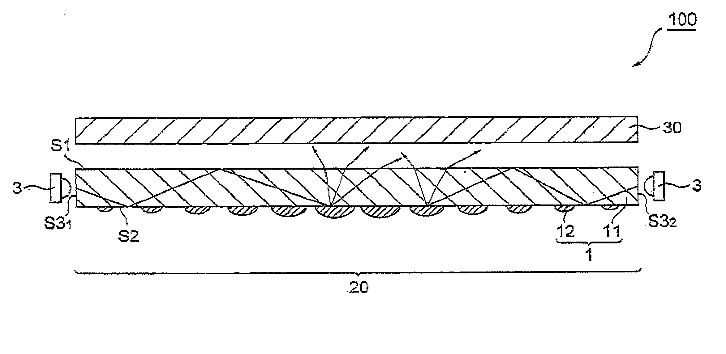
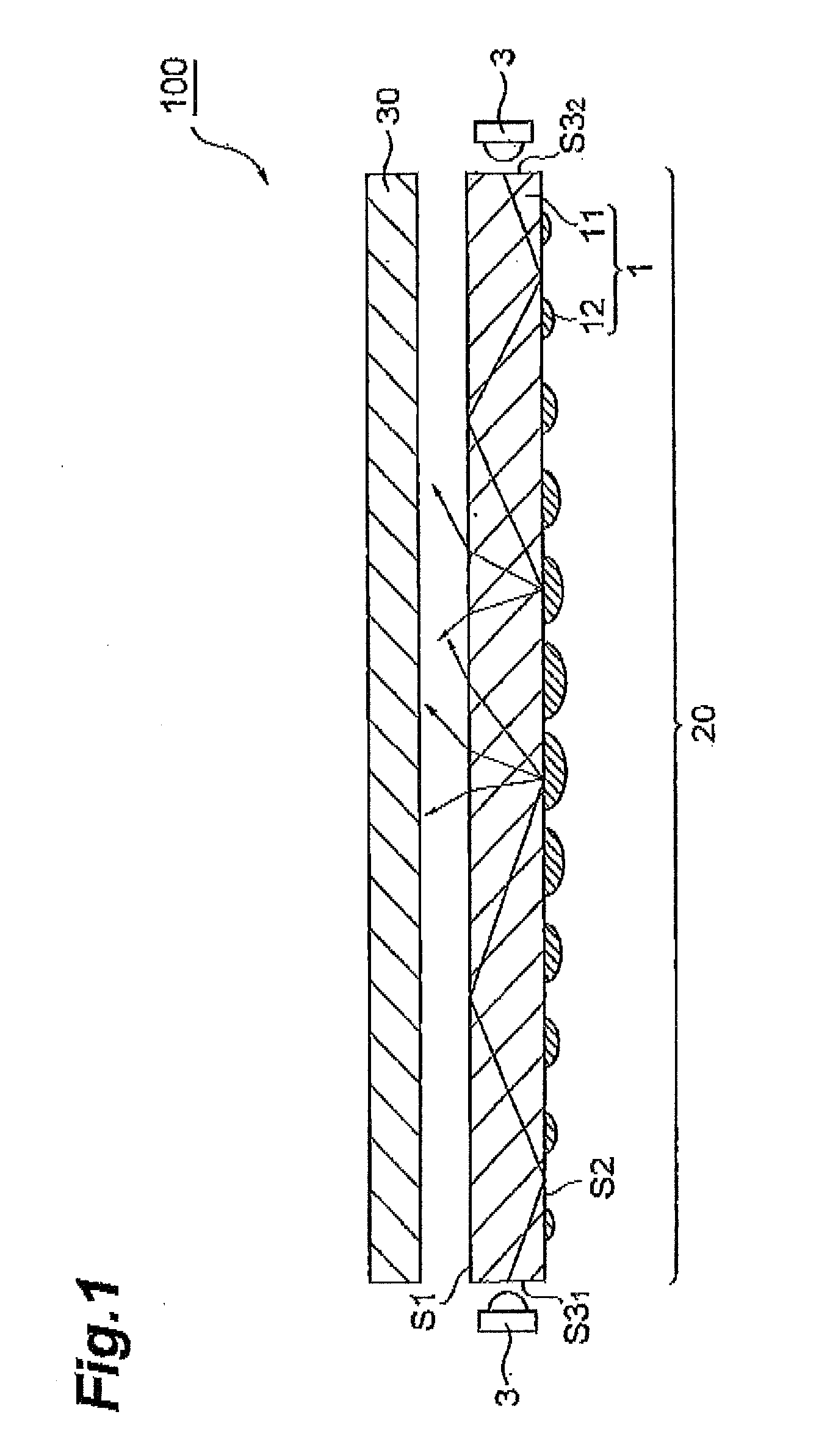
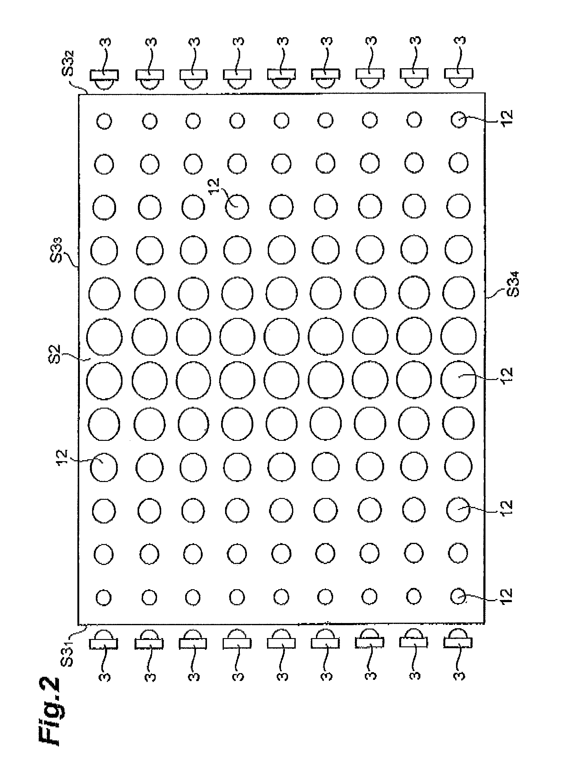
[0009]With the light guide plate according to the present invention, reflective dots constituted by the photo-curing of the ink are formed on the liquid repellent-treated rear face of the transparent resin sheet. Accordingly, since the reflective dots are suppressed from connecting with each other, a greater amount of light can be extracted from the light-emitting surface. As a result, light can be emitted from the light-emitting surface at a higher luminance.
[0010]With the light guide plate according to the present invention, preferably, the rear face is a surface that is liquid repellent-treated so that a droplet of water dropped on the rear face has a contact angle of 80 to 130 degrees. Accordingly, the reflective dots can be more reliably suppressed from connecting with each other.
[0015]In yet another aspect, the present invention relates to a surface light source device comprising: the light guide plate according to the present invention; and a light source for supplying light to the end face of a transparent resin sheet included in the light guide plate. Since the surface light source device comprises the light guide plate according to the present invention, a greater amount of light supplied from the light source can be extracted from the light-emitting surface of the transparent resin sheet. As a result, the surface light source device according to the present invention is capable of emitting light at a higher luminance.
[0019]The ultraviolet curing type ink-jet ink for a light guide plate according to the present invention is applied to become reflective dots to the liquid repellent-treated surface of the transparent resin sheet. Since the ultraviolet curing type ink-jet ink for a light guide plate according to the present invention includes the pigment, when light is supplied to a light guide plate comprising the transparent resin sheet and the reflective dots, light can be emitted from a light-emitting surface of the transparent resin sheet at a higher luminance.

Problems solved by technology

However, in a case where light is emitted using a light guide plate having reflective dots formed by inkjet printing, luminance tends to be low owing to an inability to extract sufficient light supplied to the light guide plate onto the light-emitting surface of the light guide plate.

Method used


Image

  • Light guide plate, surface light source device, transmission-type image display device, method of manufacturing light guide plate, and ultraviolet curing type ink-jet ink for light guide plate
  • Light guide plate, surface light source device, transmission-type image display device, method of manufacturing light guide plate, and ultraviolet curing type ink-jet ink for light guide plate
  • Light guide plate, surface light source device, transmission-type image display device, method of manufacturing light guide plate, and ultraviolet curing type ink-jet ink for light guide plate

Examples


examples

[0068]Hereinafter, the present invention will be described more specifically by citing examples. However, the present invention is not limited to these examples.

[0069]Light guide plates used in first to fifth examples and first to sixth comparative examples were prepared as follows.

first example

[0070](1) Liquid Repellent Treatment Agent

[0071]A liquid repellent treatment agent was prepared by removing impurities by filtration from a mixture containing: 0.52 mass % of Megaface F-556 manufactured by DIC Corporation; 15.7 mass % of aliphatic polyurethane acrylate (CN985B88 manufactured by Sartomer Japan Inc.) as a photopolymerizable oligomer; 23.02 mass % of isobornyl acrylate (Light Acrylate IBXA manufactured by Kyoeisha Chemical Co., Ltd.) and 52.34 mass % of 1,4-butanediol diacrylate (SR213 manufactured by Sartomer Japan Inc.) as a photopolymerizable monomer; and 5.23 mass % of hydroxy hexyl phenylethyl ketone (Irgacure 184 manufactured by BASF Japan Ltd.), 3.14 mass % of phenyl his (2,4,6-trimethyl benzoyl) phosphine oxide (Irgacure 819 manufactured by BASF Japan Ltd.), and 0.05 mass % of 4,4′-[10-dioxo-1,10-decanediyl]-bis(oxy)bis[2,2,6,6-tetramethyl]-1-piperidinyloxy (Irgastab UV10 manufactured by BASF Japan Ltd.) as a photopolymerization initiator.

[0072](2) Liquid Repel...

second example

[0098]A light guide plate was obtained in the same manner as in the first example with the exception of using a UV curable inkjet ink prepared by changing the pigment to 9.52 mass % of calcium carbonate particles (Silver W manufactured by Shiraishi Calcium Kaisha, Ltd.). The used pigment had a D50 of 350 nm.

[0099]The ink had a viscosity of 10.7 mPa·s at 40° C. and a surface tension, of 37.0 mJ / m2 at 25° C.

[0100]Using the obtained ink, a small sample for a measurement of spectral transmittance having a reflective coating formed by the ink was obtained by the same method as in the first example. The reflective coating of the obtained sample had a thickness of 4.8 μm. The thickness of the reflective coating was measured by the same method as in the first example.


PUM

PropertyMeasurementUnit
Fractionaaaaaaaaaa
Thicknessaaaaaaaaaa
Particle sizeaaaaaaaaaa

Abstract

The present invention provides a light guide plate capable of emitting light from a light-emitting surface at a higher luminance, a surface light source device and a transmission-type image display device having the light guide plate, a light guide plate manufacturing method, and a UV curable inkjet ink for the light guide plate. A light guide plate includes: a transparent resin sheet having a light-emitting surface that emits light incident from an end face and having a rear face on the opposite side of the light-emitting surface; and a plurality of reflective dots provided on the rear face of the transparent resin sheet and formed by photo-curing of dot-shaped ink. The ink contains a pigment, a photopolymerizable component, and a photopolymerization initiator. In addition, the rear face is a liquid repellent-treated surface.

Description

BACKGROUND OF THE INVENTION[0001]1. Field of the Invention[0002]The present invention relates to a light guide plate, a surface light source device, a transmission-type image display device, a method of manufacturing light guide plate, and a ultraviolet curing type ink-jet ink for the light guide plate.[0003]2. Description of the Related Art[0004]A transmission-type image display device such as a liquid-crystal display device generally has a surface light source device as a backlight. An edge-light type surface light source device includes a light guide plate having a transparent resin sheet and a light source for supplying a light to the end face of the transparent resin sheet. The light which has been incident from the end face of the transparent resin sheet is reflected by reflection means such as reflective dots provided on the rear face side of the transparent resin sheet, and a planar light for image display is supplied from an exit face of the light guide plate.[0005]A method...

Claims


Application Information

Patent Timeline
IPC IPC(8): F21V8/00C09D11/10B05D5/06F21S2/00F21Y103/00F21Y115/10G02F1/13357
CPCG02B6/0043G02B6/0061C09D11/322C09D11/101G02B6/0065G02B6/00G02B5/08G02F1/1335
Inventor HYAKUTA, KENTAROUTERASAWA, HIDEYUKI
Owner SUMITOMO CHEM CO LTD
Learn More