
Round Baler With Electrically Driven Roller

Active Publication Date: 2012-08-02
DEERE & CO
View PDF12 Cites 7 Cited by
  • Summary
  • Abstract
  • Description
  • Claims
  • Application Information

AI Technical Summary

Benefits of technology

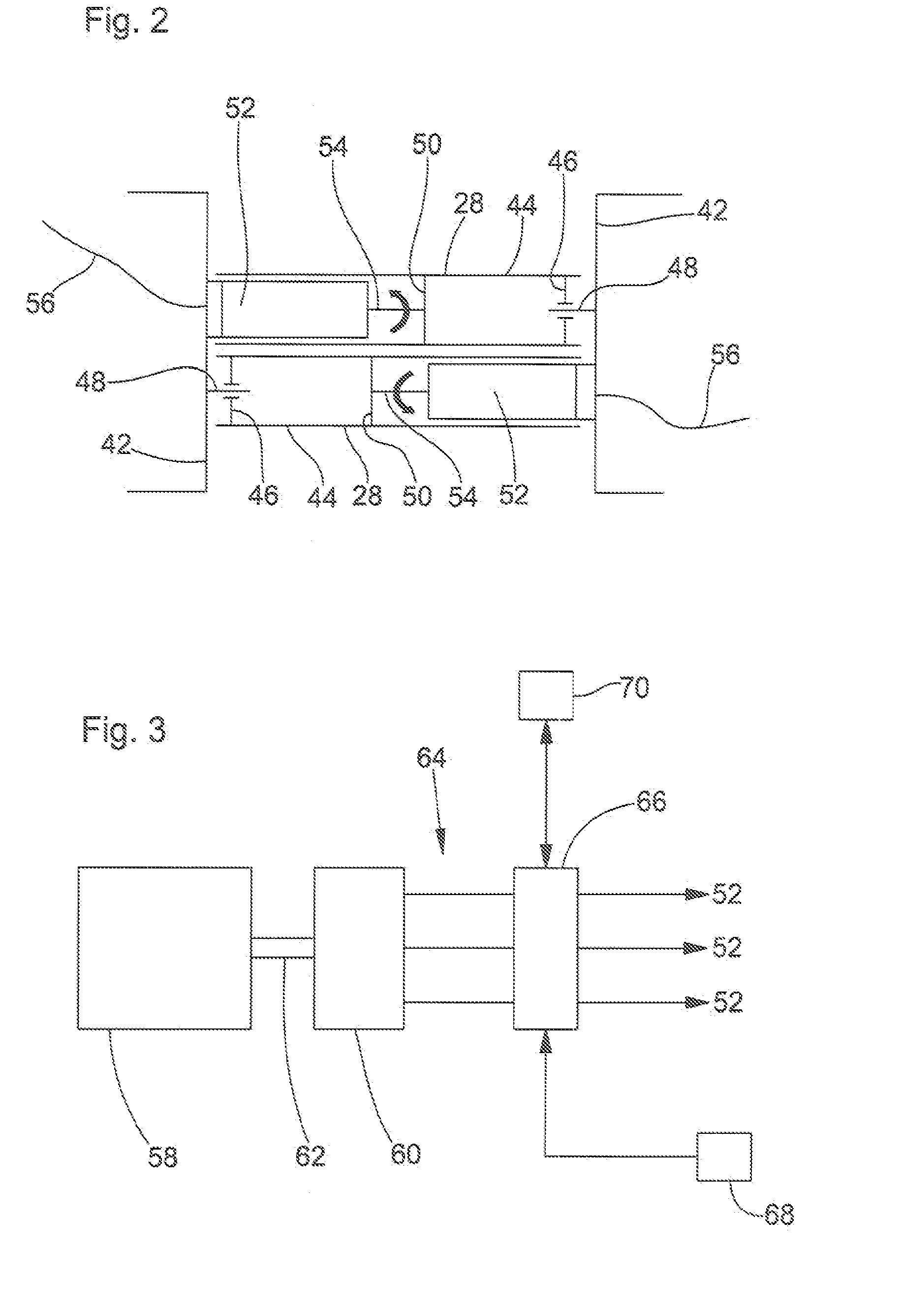
[0010]In this manner, a compact drive arrangement for the roller is obtained. A mechanical drive train between a transmission and the roller is not necessary anymore, avoiding cost, complexity, maintenance and the risk of failure of the drive train and reducing the risk of injury for the baler operator during maintenance or troubleshooting.
[0012]Further, it is proposed to connect the electric motor or motors to an electronic control unit suited for controlling the speed of the motor. The electronic control unit can be connected to a sensor that senses the rotation speed of the motor for feedback and speed control purposes, or no such sensor is used and the electronic control unit just controls one or more of the voltage, current and / or frequency of the electric power submitted to the electric motor without a feedback sensor. The electronic control unit is preferably operable to control drive the motor with a variable speed and / or in both directions. The speed of the motor can for example depend on crop conditions, like moisture or the intake rate of crop. Also, the motor can be driven with a first speed and in a first direction during a baling operation and with a second speed (which is higher or lower than during baling) and for in a second direction during a wrapping operation. The different rotation directions of the roller and thus of the bale during baling and wrapping have the advantage that the risk of unwinding a wrapping material like twine during unloading the bale can be avoided, since the bale can roll out of the baler in the same direction as it rotates during wrapping. Further, the roller and the bale can be smoothly accelerated in a start phase after a bale has been ejected.

Problems solved by technology

A disadvantage of the typical mechanical drive of the bale forming means is seen in the complexity, need for regular service, for example lubrication, and in the fixed rotation speed and direction.
The electric motors driving auxiliary components of the balers do not drive the bale forming means, but only elements that just need a limited amount of power.

Method used


Image

  • Round Baler With Electrically Driven Roller
  • Round Baler With Electrically Driven Roller
  • Round Baler With Electrically Driven Roller

Examples


Embodiment Construction

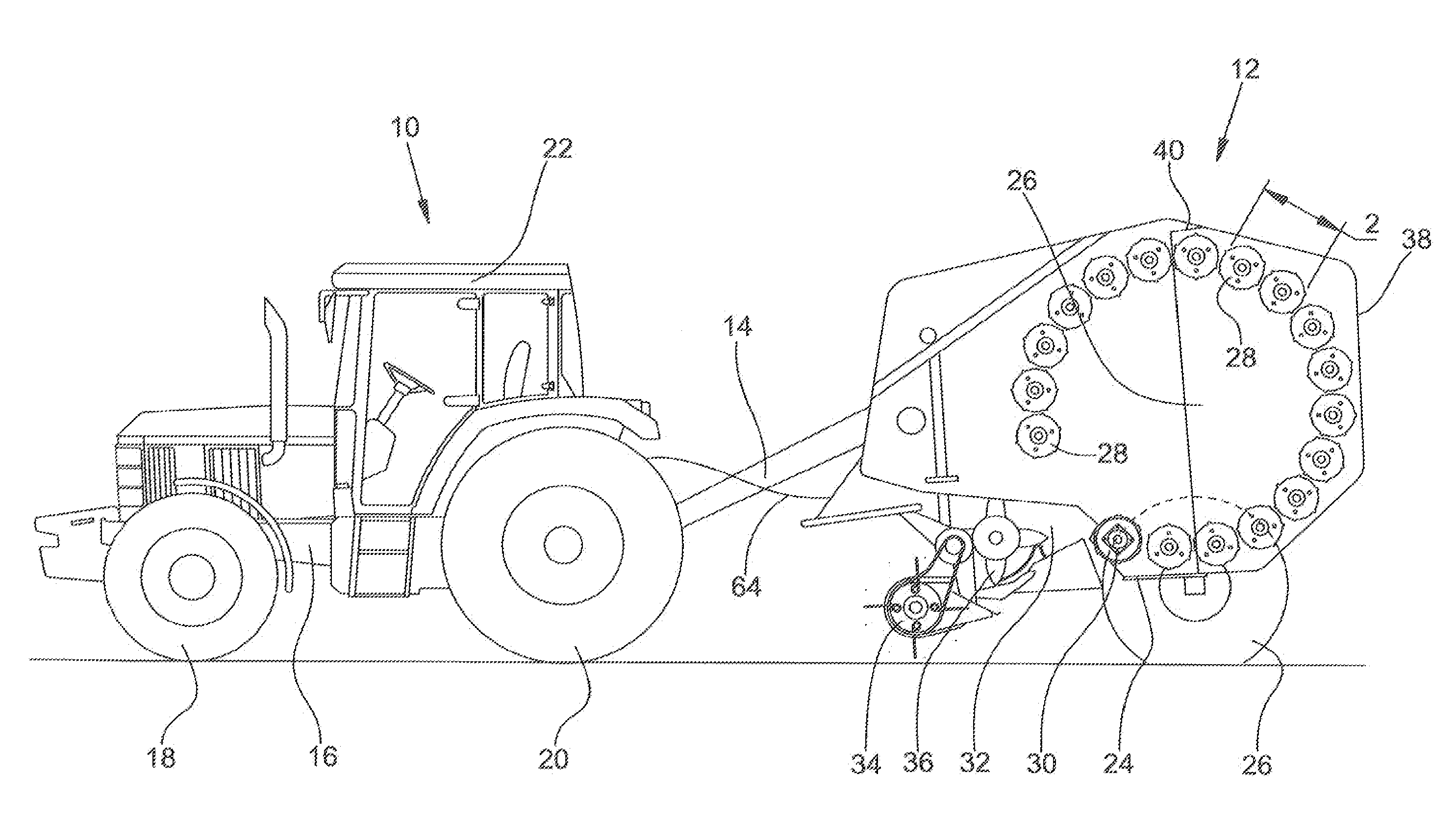
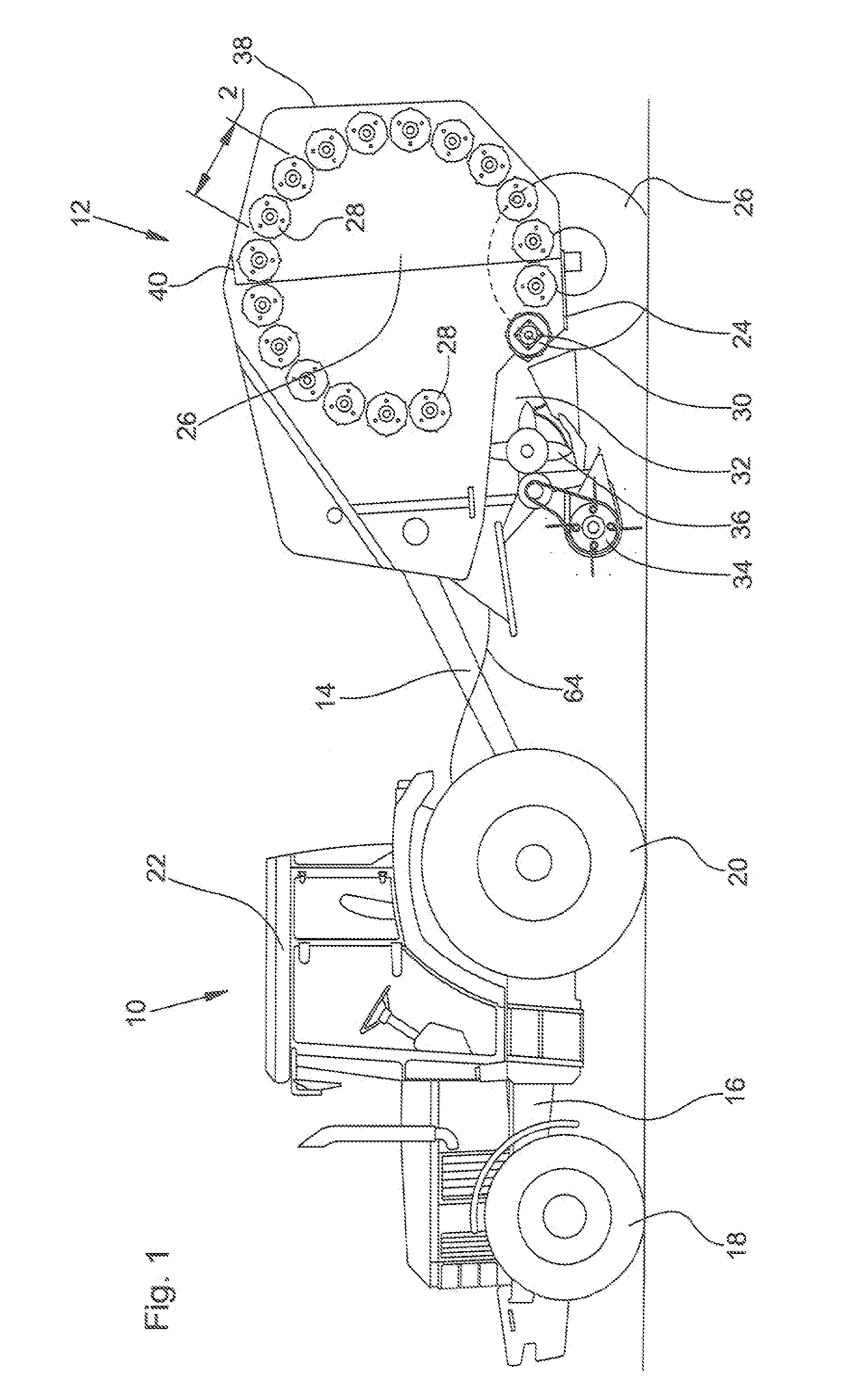
[0020]FIG. 1 shows a lateral view of a tractor 10 and a round baler 12 coupled to a drawbar hitch of the tractor 10 by means of a drawbar 14. The tractor 10 is supported on a frame 16, which is in turn supported on steerable front wheels 18 and driven rear wheels 20, and supports a cab 22 with a workstation for an operator. In the following, direction indications such as front and rear, left and right, are given with respect to the normal forward direction of the tractor 10 that goes to the left in FIG. 1.

[0021]The round baler 12 comprises a frame 24 supported on wheels 26. The frame 24 supports a cylindrical baling chamber 26 surrounded by a number of (in this embodiment seventeen) rollers 28 and a feed-in roller 30 that surround the baling chamber 26 radially, leaving an infeed gap 32 for conveying crop into the baling chamber. The crop is lifted from the ground by a overshot pick-up 34 and fed by an undershot rotor 36 into the baling chamber 26 passing the infeed gap 32. The rear...


PUM


Abstract

A round baler is provided. The round baler having a frame and a baling chamber radially surrounded by bale forming means with one or more driven rollers. An electric motor for driving the roller is disposed in the interior of the roller.

Description

FIELD OF THE INVENTION[0001]The present invention relates to a round baler comprising a frame and a baling chamber radially surrounded by baling means with one or more driven rollers.BACKGROUND OF THE INVENTION[0002]A round baler is used in agriculture to collect or gather crop lying or standing on a field and to press and bind it into a bale. The baler is towed behind a tractor and comprises a frame on which a baling chamber, radially surrounded by bale forming means, is provided. The bale forming means consist of driven rafters, belts or chains with slats or a combination of two or more of those. Crop is collected from the ground fed into the baling chamber and baled there. Finally, a bale is wrapped with a twine or net or film and deposited on the ground when it has reached a desired size, density or mass.[0003]The power for driving the bale forming means is, in the prior art, generally provided by the engine of the tractor that pulls the baler over the field. The engine drives a...

Claims


Application Information

Patent Timeline
IPC IPC(8): A01F15/07A01F15/08
CPCA01F15/085A01F2015/186A01F15/18
Inventor BIZIOREK, STEPHANEDELPHIGUE, DIDIER
Owner DEERE & CO
Learn More