
Method and Device For Controlling Engine Torque and Speed

a technology of torque and speed control and motor vehicle, which is applied in the direction of electric control, gearing control, gearing elements, etc., can solve the problems of relatively large vehicle speed change, driver difficulty in trying to keep constant speed in lower gear, etc., and achieve the effect of increasing the overall drivability of the vehicle and small speed variation

Inactive Publication Date: 2008-09-25
VOLVO LASTVAGNAR AB
View PDF11 Cites 6 Cited by
  • Summary
  • Abstract
  • Description
  • Claims
  • Application Information

AI Technical Summary

Benefits of technology

[0004]Automatic transmissions of the Automatic Mechanical Transmission (AMT) type have become increasingly common in heavy-duty vehicles as microcomputer technology has continued to advance and has made it possible, with a control computer and a number of control elements, for example servo motors, to precision-control the engine speed, the connection and disconnection of an automated clutch between engine and gearbox and coupling members of the gearbox, relative to one another, so that smooth gearshift is always obtained at the correct rev speed. The advantage with this type of automatic transmission compared to a traditional automatic transmission based on a set of planetary gears and with a hydrodynamic torque converter on the input side is firstly that, particularly as regards use in heavy vehicles, it is simpler and more robust and can be produced at substantially lower cost, and secondly that it has higher efficiency, which means the prospect of lower fuel consumption.
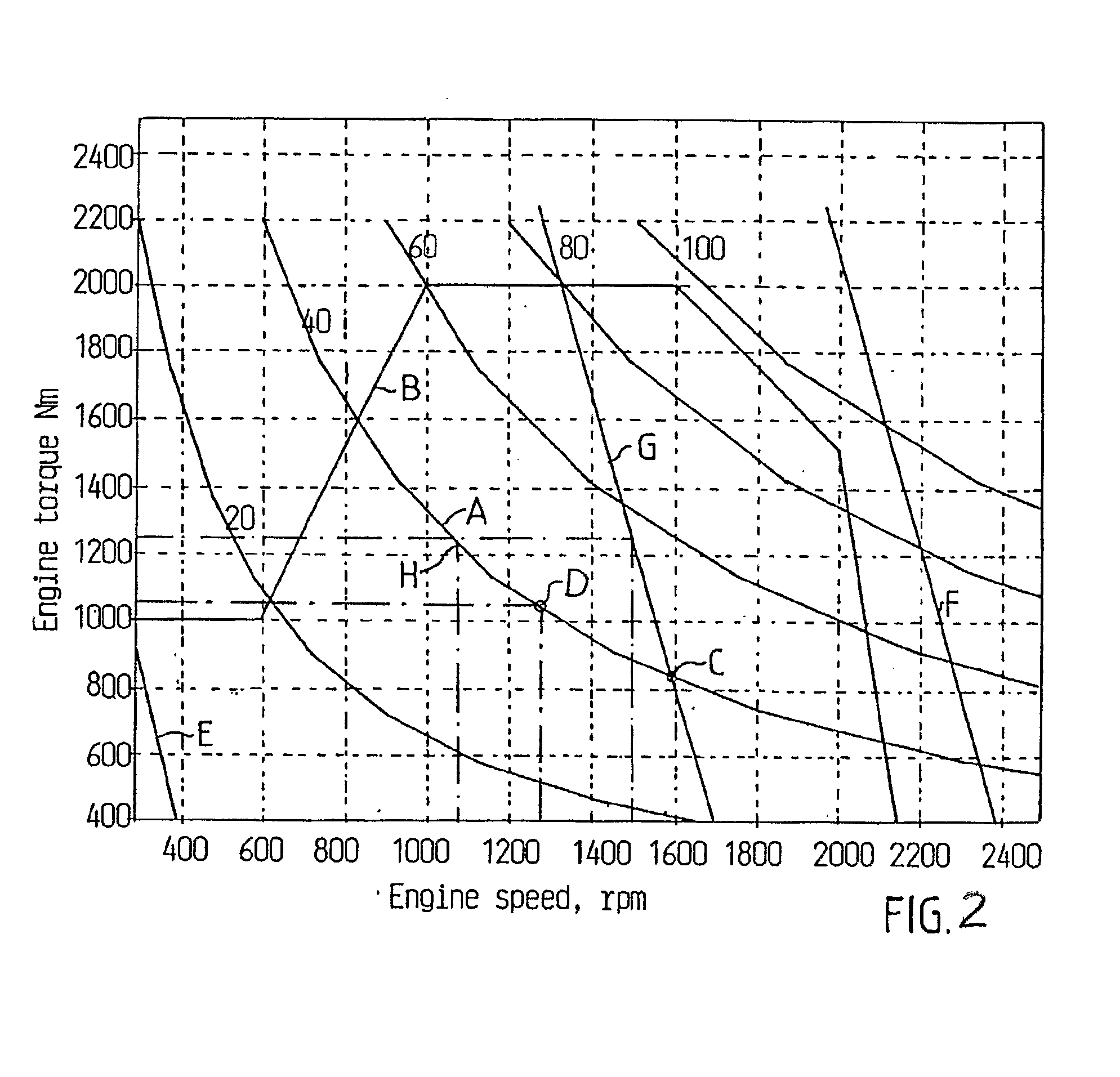
[0006]The first matrix in WO03048547 is designed so that the engine control unit provides even acceleration for each throttle control position, i.e. with as little jerking as possible when gear shifting during the acceleration. This is achieved with relatively flat throttle control curves. At the same time the control unit, after having reached the target vehicle velocity at constant throttle control position, maintains this velocity with very small deviations. This is achieved with the second matrix where throttle control position curves are as steep as possible. Steep curves provide large increases in torque for a minor drop in r.p.m. and speed.
[0008]It is desirable to improve the drivability especially at low approximately constant vehicle speeds.
[0010]The advantage with the method and device according to an aspect of the invention is that a change of the throttle control characteristics so that the controlling will be performed in accordance with the steep curves at vehicle low speed gears, gives a much smaller speed variation with a corresponding torque change compared to said flat curves. The overall drivability of the vehicle increases.

Problems solved by technology

When driving at low approximately constant vehicle speeds and the throttle being controlled via a matrix with flat throttle control curves gives the driver difficulties in trying to keep constant speed in lower gears.
This is due to that a small torque change gives a relatively big vehicle speed change.

Method used


Image

  • Method and Device For Controlling Engine Torque and Speed
  • Method and Device For Controlling Engine Torque and Speed
  • Method and Device For Controlling Engine Torque and Speed

Examples


Embodiment Construction

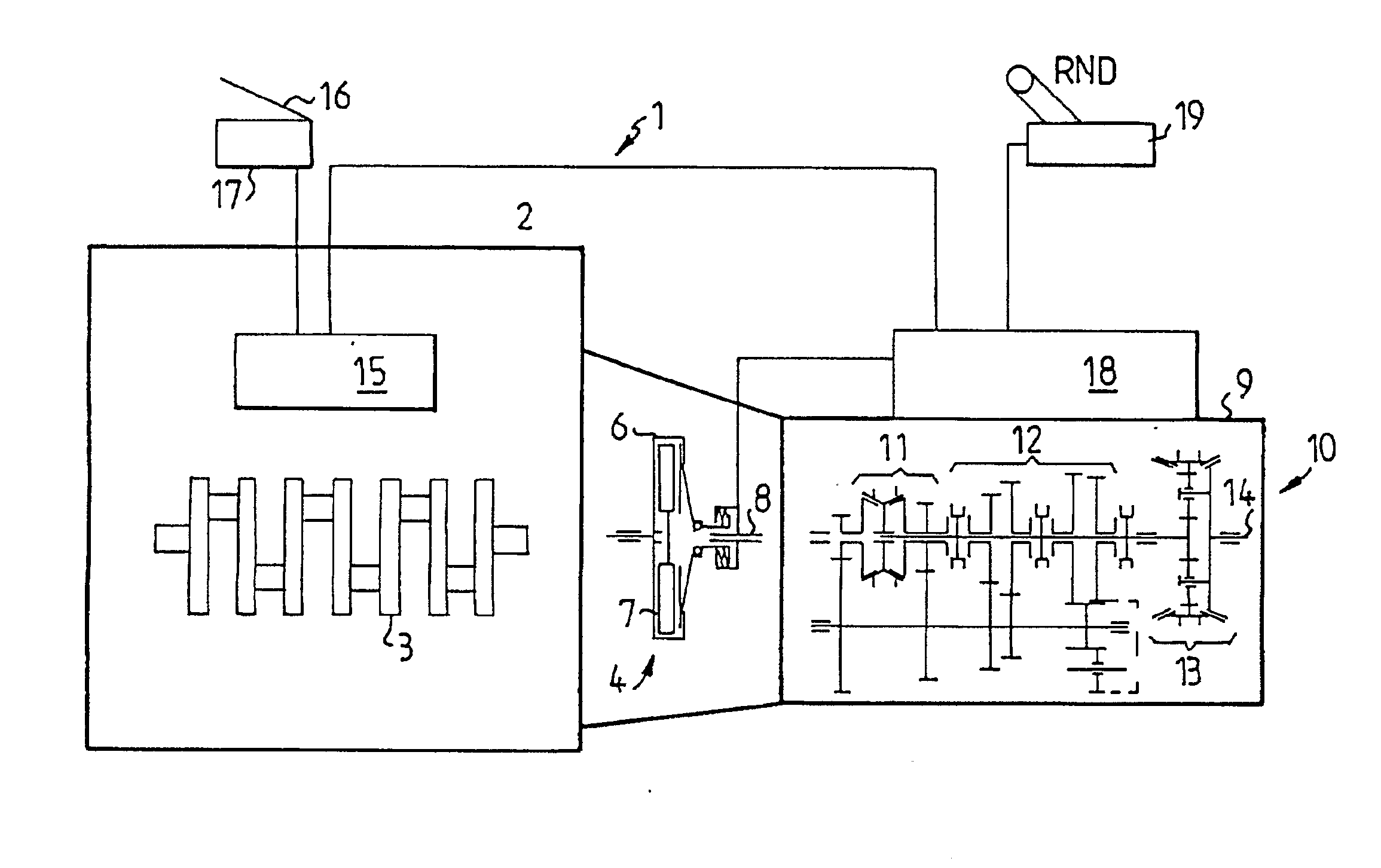
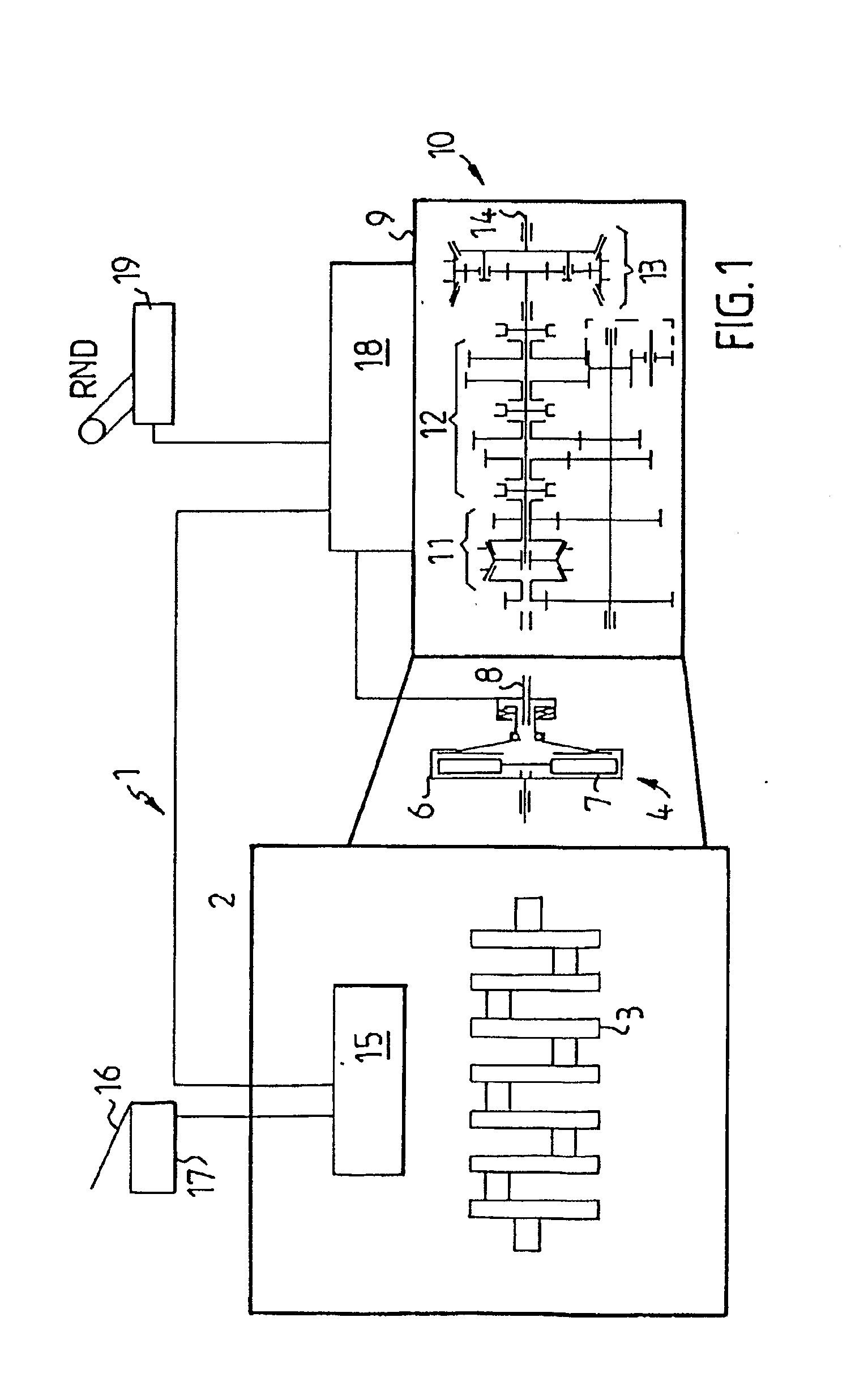
[0015]The drive unit 1 shown in FIG. 1 comprises in the embodiment shown a six-cylinder engine 2, e.g. a diesel engine, the crankshaft 3 of which is coupled to an automated drive disc clutch generally designated 4, which is enclosed in a clutch housing 6. The crankshaft 3 is non-rotatably joined to the clutch housing 6 of the clutch 4, while its disc 7 is non rotatably joined to an input shaft 8, which is rotatably mounted in the housing 9 of an autoshift gearbox generally designated 10, which in the example has a splitter group 11, a main group 12 and a range group 13. The gearbox 10 has an output shaft 14 intended to be drivably coupled to the vehicle driving wheels (not shown), e.g. via a propeller shaft (not shown). The engine 2 is controlled by an electronic engine control unit 15, which can comprise a microprocessor, in response to signals from a position sensor 17 coupled to a throttle control 16, e.g. an accelerator pedal. The transmission 10 is controlled by a transmission ...


PUM


Abstract

A method and device for modifying throttle control characteristics of a throttle control in a vehicle, the vehicle including an engine coupled to engine driven vehicle wheels via a stepped gear mechanical transmission, and where requested engine torque at a given engine speed of the engine is controlled as a function of positions of the throttle control. When sensing a gear shift to a vehicle high speed gear, a control unit modifies the characteristics so the engine torque and engine speed will be controlled via said throttle control along a first set of relatively flat curves, when the curves are plotted in a diagram with engine torque on the y-axis and engine speed on the x-axis. When sensing a gear shift to a vehicle low speed gear, the characteristics are modified so the engine torque and engine speed will be controlled via the throttle control along a second set of curves that are steeper than the first set of curves, so that when driving with a vehicle low speed and for a certain change in engine speed, a greater change in torque will be provided than when controlling is done in accordance with the first set of curves.

Description

[0001]The present application is the U.S. National Stage application of PCT / SE2006 / 001008, filed Sep. 1, 2006, which claims priority of U.S. Provisional Application No. 60 / 596,214, filed Sep. 8, 2005.BACKGROUND AND SUMMARY[0002]The present invention relates to a method and drive unit for a motor vehicle, comprising an internal combustion engine, a manually adjustable throttle control and an electronic engine control unit for controlling the engine torque and engine speed, and to which the throttle control is electrically connected, and in which engine control unit a first and a second throttle control characteristics are stored. Said engine torque and engine speed are controlled via said throttle control and one of said throttle control characteristics.[0003]It has become more and more common in motor vehicles of late to replace a mechanical wire linkage system coupling the accelerator pedal position or its movement to the engine throttle and fuel engine system with electronic trans...

Claims


Application Information

Patent Timeline
IPC IPC(8): F16H59/24
CPCF02D11/105Y10T477/6933F02D41/2422F02D41/0225
Inventor BERGLUND, SIXTENTEMPLIN, PETER
Owner VOLVO LASTVAGNAR AB
Learn More