
System and method for electronic signature via proxy

a technology of electronic signature and proxy, applied in the field of system and method of electronic signature via proxy, can solve the problem of entanglement of the rapid spread of the use of electronic signatur

Inactive Publication Date: 2012-07-26
FELDBAU MICHAEL
View PDF5 Cites 96 Cited by
  • Summary
  • Abstract
  • Description
  • Claims
  • Application Information

AI Technical Summary

Benefits of technology

[0011]According to the present invention, people who do not own electronic signature means, may now fill-in electronic forms and applications and send them promptly for example by e-mail to their proxy, which in turn signs them on behalf of the sender, and optionally submits the signed documents to a designated recipient. The proposed solution may be suitable for various applications requiring a user's signature, including, inter alia, signing of electronic contracts, electronic orders, electronic invoices, electronic tax reports, electronic official forms, medical prescriptions and effectively any admissible electronically signed document.

Problems solved by technology

Technical problems mainly hinder the quick spreading of the usage of electronic signatures.
The problem preventing spreading of use of electronic signatures by the public seems to lie in the implementation of electronic signing: people need to register with a certified registrar, go through a tedious process of authentication, obtain some sort of “secret key”, which typically involves some piece of hardware such as an electronic card, a card reader, a USB dongle or alike, install some software and a key on one's computer, learn how to operate and utilize the private key, and worse yet—be bound to the computer having the card reader or the dongle to be able to use the electronic private key in order to electronically sign documents.

Method used


Image

  • System and method for electronic signature via proxy
  • System and method for electronic signature via proxy
  • System and method for electronic signature via proxy

Examples


Embodiment Construction

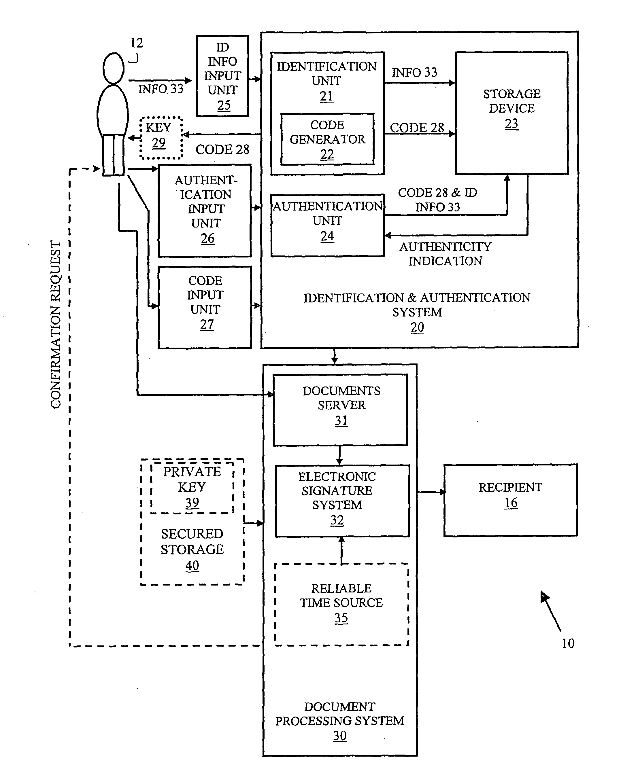
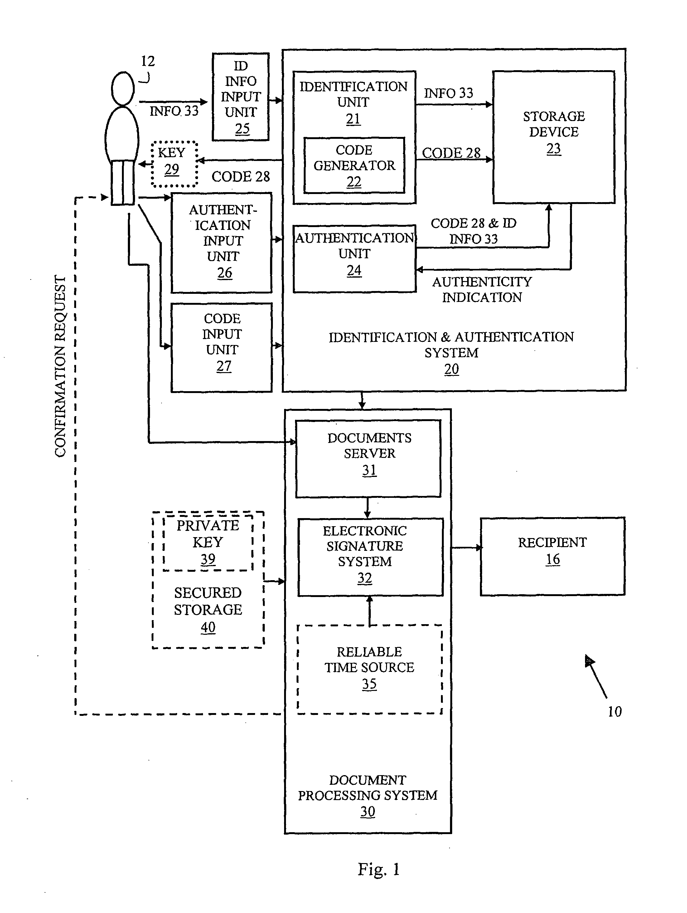
[0018]In the following detailed description, numerous specific details are set forth in to order to provide a thorough understanding of the invention. However, it will be understood by those skilled in the art that the present invention may be practiced without these specific details. In other instances, well-known methods, procedures, and components have not been described in detail so as not to obscure the present invention. Reference is made to FIG. 1, which is a schematic block diagram of a system for signing of documents via proxy, according to one embodiment of the present invention. Signature via proxy system 10 may comprise identification and authentication sub-system 20 and a documents processing sub-system 30.

[0019]Identification and authentication system 20 may comprise identification unit 21 adapted to receive identification information 33 such as an e-mail address from user 12, via information input means 25, process the information 33, optionally store a representation...


PUM


Abstract

A system and method are disclosed for providing proxy signature to user documents comprised of an identification and authentication system, input means to enable providing identification information by the user to the identification and authentication system, authentication input means to enable providing authentication information by the user to the system, an electronic signature system, and a documents server for receiving documents from the user for electronic signature The system may comprise a storage device, an identification sub-system adapted to receive identification information from said user via said information input means and store the identification information in the storage device, an authentication sub-system adapted to authenticate the identity of the user based on information stored in said storage device and information provided by the user during authentication process via said authentication information input means The electronic signature system is adapted to apply a signature to documents provided by the user.

Description

BACKGROUND OF THE INVENTION[0001]Current legislation related to electronic signatures provides the framework whereby people can electronically sign electronic documents, which in turn are accepted and treated as if they were original signed paper documents.[0002]In the context of the present invention, the term “electronic signature” refers to the electronic expression of a lawful signature, which may be an electronic sound, symbol, data or process, attached to or logically associated with a record and executed or adopted by a person with the intent to sign a record.[0003]Digital Signatures are implementations of electronic signatures that are widely used. Typically, Digital Signatures are generated by encrypting digital data or a hash thereof with a private (secret) key. The private key is typically stored in a secure location and / or on a secure device, and often further requires the use of a password to gain access to it. When implementing what is known as Symmetric Cryptosystem, ...

Claims


Application Information

Patent Timeline
Patent Type & Authority Applications(United States)
IPC IPC(8): H04L9/32
CPCH04L63/126H04L9/3247H04L2209/805H04L2209/76H04L9/3297
Inventor FELDBAU, MICHAEL
Owner FELDBAU MICHAEL
Learn More