Acoustic reflectors

a technology of acoustic reflectors and markers, applied in the direction of sound producing devices, transmission, coatings, etc., can solve the problems of less suitable commercial applications for reflectors, and achieve the effects of reducing thickness, reducing resistance to internal pressure, and reducing strength

Active Publication Date: 2012-07-26
SALT AVIATION RECOVERY ASSISTANCE LTD
View PDF8 Cites 18 Cited by
  • Summary
  • Abstract
  • Description
  • Claims
  • Application Information

AI Technical Summary

Benefits of technology

[0060]Where the shell is made of a material which may fail under internal pressures as a result of decompression of the reflector when it is raised to the surface the shell halves can be provided with a region at their joint of reduced resistance to internal pressure.
[0061]In the case of hemispheres with a spin weld between them the circumference of the spin welded area may be of reduced thickness or of reduced strength.

Problems solved by technology

Outside this range reflectors are less suitable for commercial application as the diameter of the reflector has to increase significantly to compensate for reduced target strength.

Method used


Image

  • Acoustic reflectors
  • Acoustic reflectors
  • Acoustic reflectors

Examples


Embodiment Construction

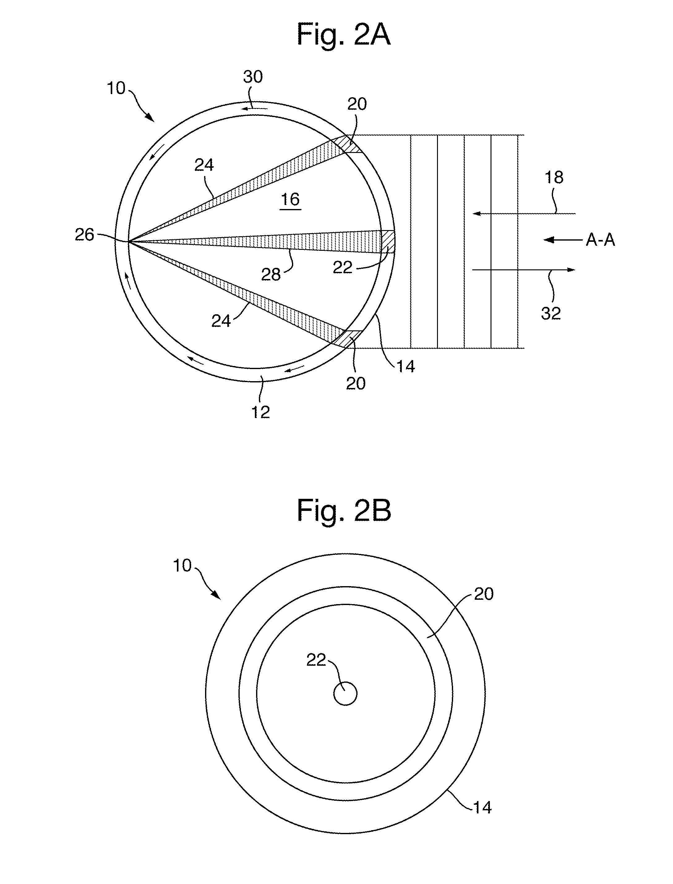
[0095]Referring to FIGS. 1A and 1B, an acoustic reflector 10 comprises a spherical shell 12 surrounding a core 16. The shell 12 is formed from 25% glass fibre reinforced polyphthalamide. The core 16 is RTV 12.

[0096]Acoustic waves 18, transmitted from an acoustic source (not shown), are incident as shown the outside wall 14 of shell 12. The shell has acoustic transmission window 20, its exact diameter being dependent on the diameter of the shell, acoustic waves incident on this window 20 are transmitted through shell 12 and into core 16.

[0097]The incident acoustic wave striking windows 20 pass through the shell the shell 12 into core 16: to be focused a focal point 26 on the inside of shell 12 opposite window 20 to be reflected back to the window.

[0098]A portion of the incident waves 18 is coupled into the shell 12 and generates both elastic and transverse waves 30 which are guided within the shell 12 around its circumference. The strongest waves are the elastic ones. For reflectors ...


PUM

PropertyMeasurementUnit
diameteraaaaaaaaaa
diameteraaaaaaaaaa
temperatureaaaaaaaaaa

Abstract

An acoustic reflector comprises a shell surrounding a solid joint free core, said shell being capable of transmitting acoustic waves incident on the surface of the shell into the core to be focused and reflected from an area of the shell located opposite to the area of incidence so as to provide a reflected acoustic signal output from the reflector. The ratio of the speed of sound wave transmission in the shell to the average speed of the wave transmission in the core is preferably in the range of 2.74 to 3.4, inclusive or a multiple thereof with best result in the range of 2.74 to 2.86 inclusive.

Description

1. CROSS-REFERENCES TO RELATED APPLICATIONS[0001]This application is a Continuation-in-Part of:[0002]a) International Application No. PCT / GB2010 / 051161 filed in English on 16 Jul. 2010 claiming priority to GB Applications Nos:[0003]0913199.6—29 Jul. 2009[0004]0913200.2—29 Jul. 2009[0005]0913201.0—29 Jul. 2009[0006]0913203.6—29 Jul. 2009[0007]0913387.7—31 Jul. 2009[0008]0913388.8—31 Jul. 2009[0009]0914462.7—19 Aug. 2009[0010]0915073.1—1 Sep. 2009[0011]0917714.8—12 Oct. 2009[0012]0921397.6—7 Dec. 2009[0013]0921399.2—7 Dec. 2009[0014]1001810.9—4 Feb. 2010[0015]1006093.7—13 Apr. 2010[0016]b) GB Application No. GB Application No. 1121116.6 filed 8 Dec. 2011.The entire contents of these applications are incorporated herein by reference.2. BACKGROUND OF THE INVENTION[0017]1. Field of the Invention[0018]This invention related to passive acoustic reflectors and markers for underwater use.[0019]2. Discussion of Prior Art[0020]Passive acoustic reflectors are known, for example, from UK Patent ...

Claims


Application Information

Patent Timeline
Patent Type & Authority Applications(United States)
IPC IPC(8): G10K11/00B29C39/00H04B1/59
CPCB29C39/003G10K11/205B29K2083/00B29K2009/00
Inventor TILTMAN, CARL PETERTULLOCH, ANDREW MALCOLM
Owner SALT AVIATION RECOVERY ASSISTANCE LTD
Why Eureka
Try Eureka