Eureka AIR delivers breakthrough ideas for toughest innovation challenges, trusted by R&D personnel around the world.

Energy Supply System

a technology of energy supply and energy storage, applied in the direction of transportation and packaging, arrangement of several simultaneous batteries, and propulsion using engine-driven generators, can solve the problems of inconsistent heat up and reduce the efficiency of the overall system, and achieve the effect of improving the efficiency of a system having a plurality of series-connected energy storag

Inactive Publication Date: 2012-07-26
ROBERT BOSCH GMBH
View PDF0 Cites 103 Cited by
  • Summary
  • Abstract
  • Description
  • Claims
  • Application Information

AI Technical Summary

Benefits of technology

[0005]The present invention is based on the finding that the efficiency of a system having a plurality of series-connected energy storages may be improved if the energy storages, for example, batteries or battery cells, are exposed to loads individually, for example, consistent with the particular age condition or other boundary conditions. To this end, each energy storage, which may be made up of one or multiple energy storage modules or energy storage cells, may be provided with an equipotential bonding DC chopper, also referred to as a DC / DC converter (DC: direct current). If the DC choppers are connected in series, for example, on the output side, each energy storage may be exposed to a load by specifically activating each DC chopper in conformity with the energy storage's present load capacity and thus operated optimally. Thus, the energy storages are not operated directly, but instead indirectly through one or multiple DC choppers which convert the voltage of the energy storages into, for example, a selectable output voltage as a step-up converter or a step-down converter.
[0007]According to one specific embodiment, the output voltages of a plurality or the number of DC choppers are each settable according to a setpoint input, in order to expose the energy storages to a load individually, in particular differently, under the same current load of the DC choppers. This produces an advantageous distribution of the loads to individual energy storages.

Problems solved by technology

Furthermore, the battery cells are often thermally coupled to the environment in different ways, so that they can also heat up inconsistently.
However, the cells are not exposed to loads as a function of their particular load capacity, which can result in reduced efficiency of the overall system.

Method used


Image

  • Energy Supply System
  • Energy Supply System
  • Energy Supply System

Examples


Embodiment Construction

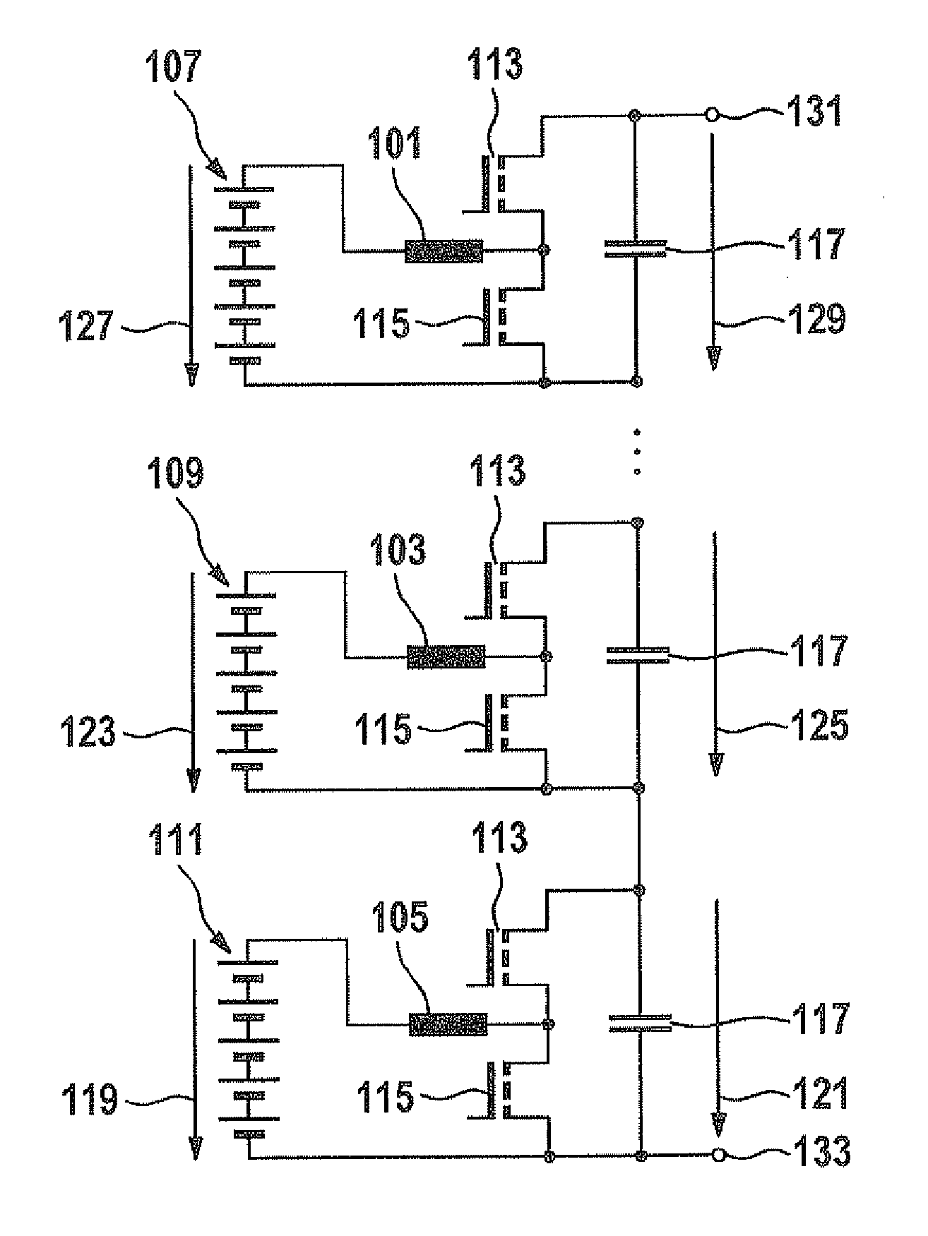
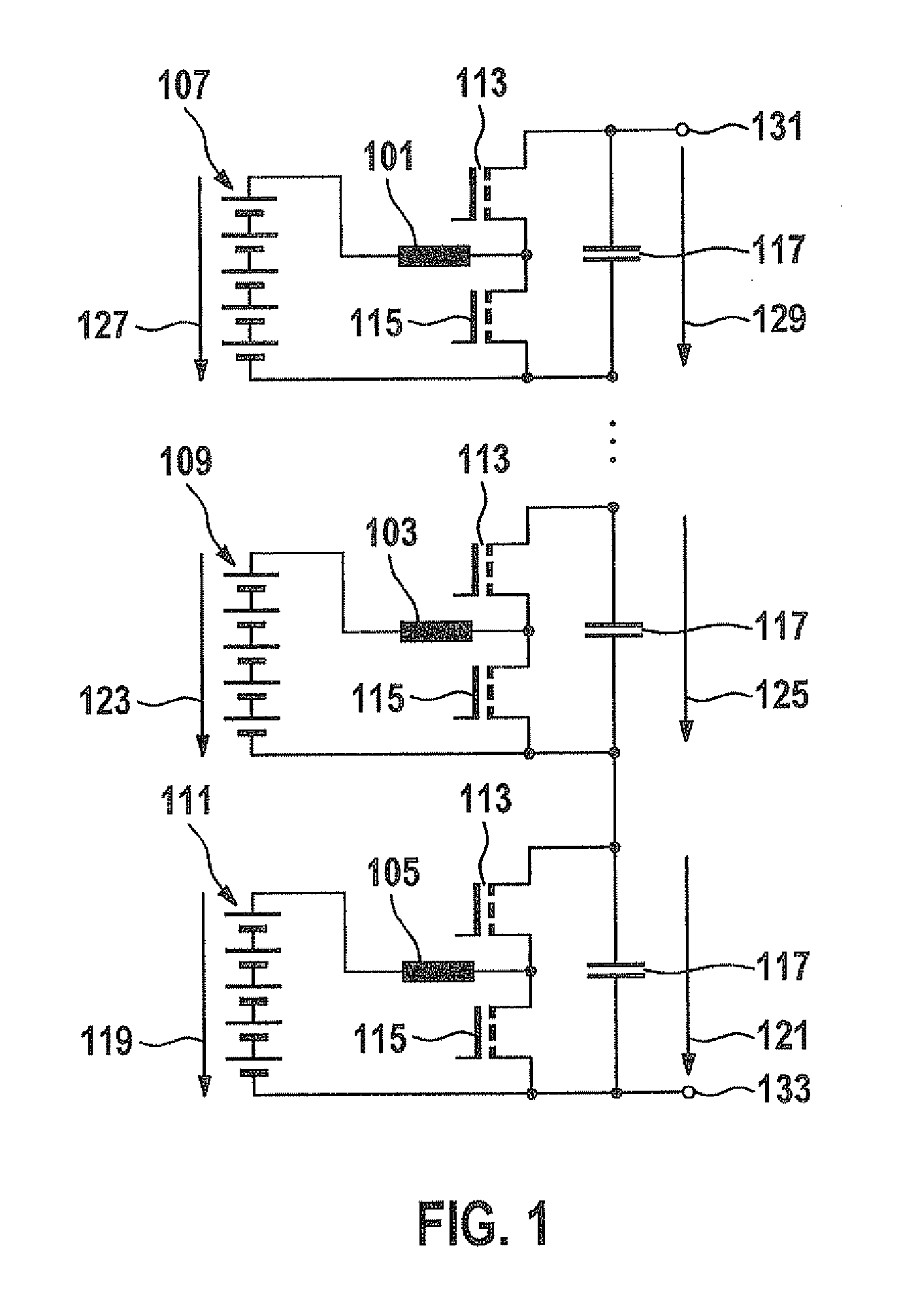
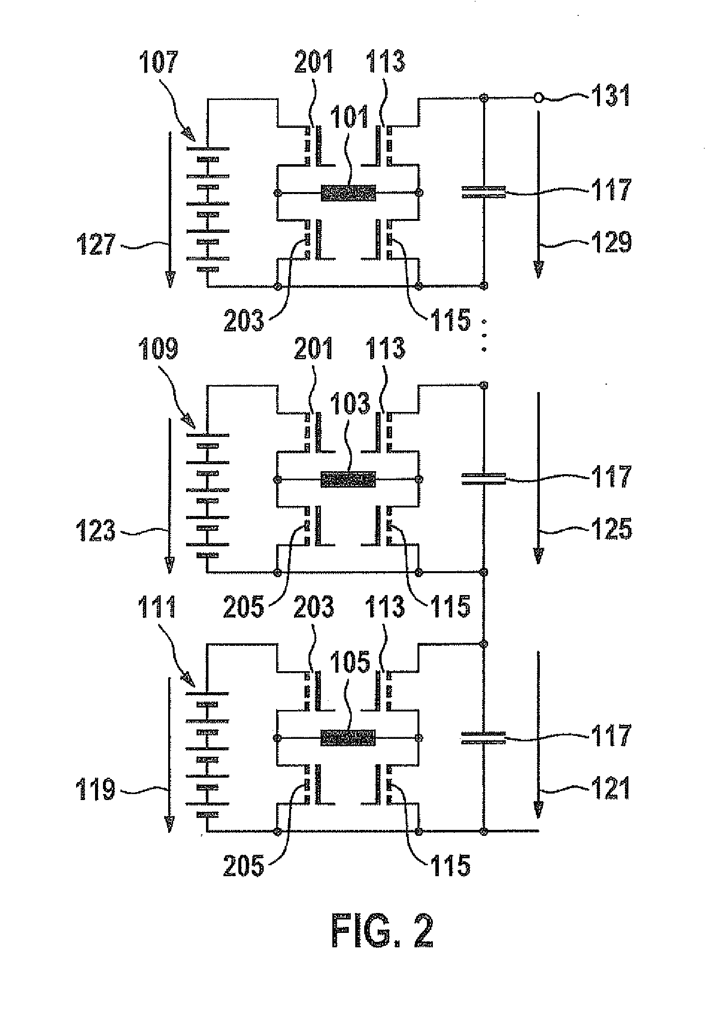
[0020]FIG. 1 shows an energy supply system having a number of DC choppers 101, 103 and 105. DC chopper 101 is connected downstream from an energy storage 107, DC chopper 103 is connected downstream from an energy storage 109 and DC chopper 105 is connected downstream from an energy storage 111. Each energy storage, for example, may be made up of one or multiple storage cells. The energy storages may be, for example, vehicle batteries.

[0021]On the output side, DC choppers 101, 103 and 105 are each connected to a circuit configuration including two transistors 113 and 115. On the output side, a smoothing capacitor 117 is provided optionally in each case.

[0022]DC choppers 101 through 105 shown in FIG. 1 are preferably connected in series, for example, input voltage 119, Umod1, supplied to DC chopper 105 on the input side by energy storage 111, being converted into an output voltage 121, Uzkmod1. Accordingly, input voltage 123, Umod2, which is supplied to the DC chopper on the input sid...


PUM


Abstract

An energy supply system has a number of DC choppers for converting the input voltages applied in each case into output voltages, and a number of energy storages for providing the input voltages, an energy storage being assigned to each DC chopper. An output voltage of at least one of the number of DC choppers is settable as a function of a setpoint input in order to expose the energy storage assigned to the at least one DC chopper to a load individually.

Description

BACKGROUND OF THE INVENTION[0001]1. Field of the Invention[0002]The present invention relates to energy supply using energy storages, e.g., using electric vehicle or hybrid vehicle batteries.[0003]2. Description of Related Art[0004]Known electric vehicle or hybrid vehicle batteries are made up of individual battery cells, which always have certain individual variations, for example, with respect to efficiency. Furthermore, the battery cells are often thermally coupled to the environment in different ways, so that they can also heat up inconsistently. To achieve a uniform load of the battery cells, they are usually connected in series so that the same current flows through each battery cell. However, the cells are not exposed to loads as a function of their particular load capacity, which can result in reduced efficiency of the overall system.BRIEF SUMMARY OF THE INVENTION[0005]The present invention is based on the finding that the efficiency of a system having a plurality of series-...

Claims


Application Information

Patent Timeline
Patent Type & Authority Applications(United States)
IPC IPC(8): H02J1/00B60L50/15
CPCH02J7/0065H02M3/158Y02T10/7055H02M2001/0077H02J7/0019H02J2207/20Y02T10/70H02M1/0077H02J7/04
Inventor SPANNHAKE, STEFANFASSNACHT, JOCHENHEUSEL, JOCHEN
Owner ROBERT BOSCH GMBH
Why Eureka
Eureka Blog
Learn More