
Semiconductor device and semiconductor device package

a semiconductor device and semiconductor technology, applied in semiconductor devices, semiconductor/solid-state device details, electrical devices, etc., can solve the problems of increased transmission loss, signal waveform quality deterioration, and reliability of semiconductor devices or semiconductor device packages deterioration, so as to prevent reliability deterioration

Inactive Publication Date: 2012-07-26
HITACHI LTD
View PDF0 Cites 29 Cited by
  • Summary
  • Abstract
  • Description
  • Claims
  • Application Information

AI Technical Summary

Benefits of technology

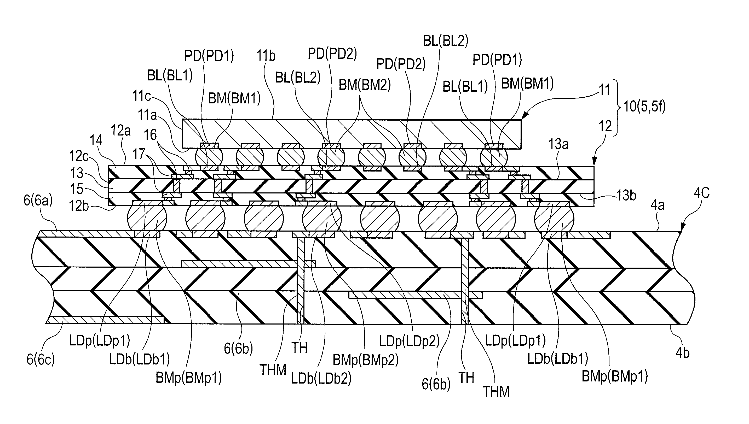
[0005]As semiconductor devices have a higher functionality, there is a tendency that they use a larger number of external terminals. When many external terminals are provided in a semiconductor device, the so-called area array type of semiconductor device is advantageous in avoiding an increase in the area for mounting external terminals because in this type of semiconductor device, the external terminals are arranged in a grid pattern (array or matrix pattern) in the external terminal mounting surface of a wiring substrate (interposer substrate) with a semiconductor chip mounted thereon so the area of the external terminal mounting surface is used effectively.
[0011]The present invention has been made in view of the above problem and has an object to provide a technique which prevents deterioration in the reliability of a semiconductor device or semiconductor device package which transmits plural differential signals.
[0016]The invention prevents deterioration in the reliability of a semiconductor device or semiconductor device package which transmits plural differential signals.

Problems solved by technology

In a semiconductor device which transmits plural differential signals, the reliability of the semiconductor device or semiconductor device package may deteriorate depending on how the external terminals of the device are arranged.
This is because if there is a mismatch in the characteristic impedances of the differential pair, the signal waveform quality deteriorates due to increased transmission loss or reflections.

Method used


Image

  • Semiconductor device and semiconductor device package
  • Semiconductor device and semiconductor device package
  • Semiconductor device and semiconductor device package

Examples


Embodiment Construction

[0032]Description Rules in this Specification

[0033]Descriptions of the preferred embodiments will be made below separately or in different sections as necessary, but such descriptions are not irrelevant to each other unless otherwise specified. One description may be, in whole or in part, a variation or a detailed or supplementary form of another. Also, in the preferred embodiments described below, even when a specific number is indicated for an element (the number of pieces, numerical value, quantity, range, etc.), it is not limited to the specific number unless otherwise specified or theoretically limited to the number; it may be larger or smaller than the specific number.

[0034]In the preferred embodiments described below, constituent elements (including constituent steps) are not necessarily essential unless otherwise specified or theoretically essential. Similarly, in the preferred embodiments described below, when a specific form or positional relation is indicated for a consti...


PUM


Abstract

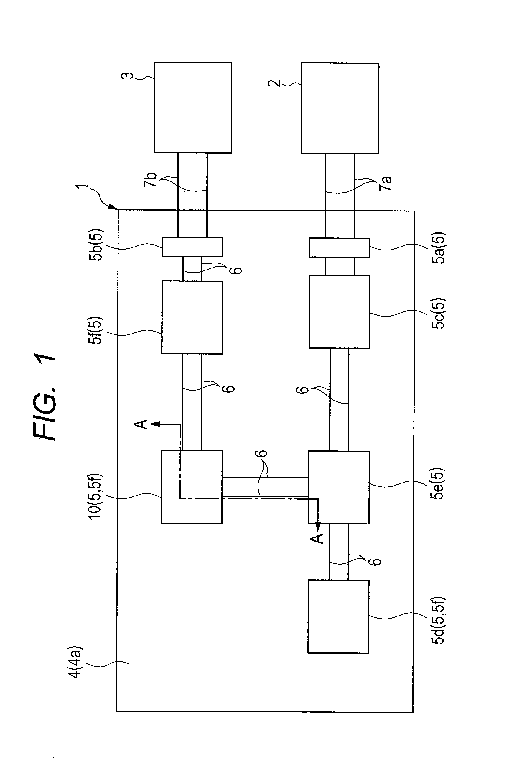
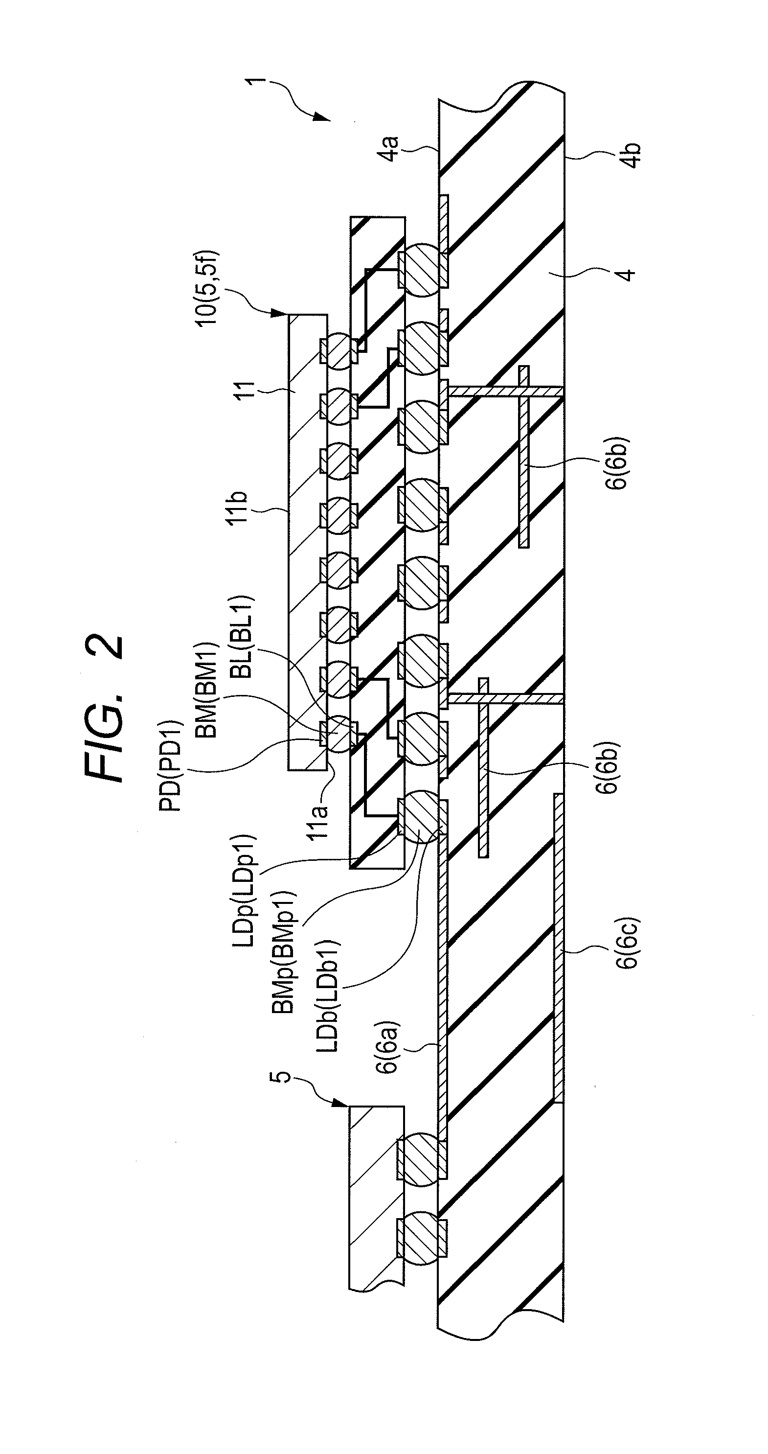
A semiconductor device or semiconductor device package for transmitting a plurality of differential signals, the reliability of which hardly deteriorates. The semiconductor device is an area array semiconductor device in which a plurality of lands (external terminals) including a plurality of lands for transmitting a plurality of differential signals are arrayed in a matrix pattern in the back surface of a wiring substrate. Some of the lands are located in the outermost periphery of the matrix pattern. Some others of the lands are located inward of the outermost periphery of the matrix pattern and in rows next to the outermost periphery. The spacing between lands in a second region between the lands located in the rows next to the outermost periphery and the side surface of the wiring substrate is larger than in a first region in the outermost periphery.

Description

CLAIM OF PRIORITY[0001]The present application claims priority from Japanese patent application JP 2011-013731 filed on Jan. 26, 2011, the content of which is hereby incorporated by reference into this application.FIELD OF THE INVENTION[0002]The present invention relates to a semiconductor device and a semiconductor device package with the same mounted therein and more particularly to technology useful for semiconductor devices such as communication devices which transmit differential signals.BACKGROUND OF THE INVENTION[0003]Japanese Unexamined Patent Application Publication No. 2004-158754 describes a BGA (ball grid array) semiconductor device in which, between a pair of bump electrodes connected to coupled differential signal lines and a wiring substrate, no other bump electrodes are provided.SUMMARY OF THE INVENTION[0004]In recent years, in order to improve the performance of computer and communication systems, efforts have been made towards higher speed and multilane interfacing...

Claims


Application Information

Patent Timeline
IPC IPC(8): H01L23/48
CPCH01L23/49822H01L23/50H01L2224/16227H01L23/49833H01L2224/16225H01L23/49827H01L2924/15311H01L2224/05571H01L2224/05573H01L2924/00014H01L2224/05599
Inventor TSUGE, MASATOSHIKUWATA, MAKOTO
Owner HITACHI LTD
Learn More