
Multiple Induction Electric Motor and Vehicle

a technology of electric motors and electric motors, applied in the field of electric motors, can solve the problems of varnish vacuum pressure impregnation on the wire windings,

Inactive Publication Date: 2012-07-26
MULTIPLE ELECTRIC SYST L L C
View PDF3 Cites 26 Cited by
  • Summary
  • Abstract
  • Description
  • Claims
  • Application Information

AI Technical Summary

Benefits of technology

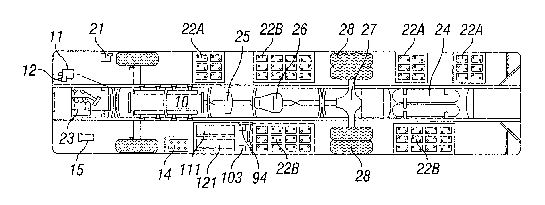
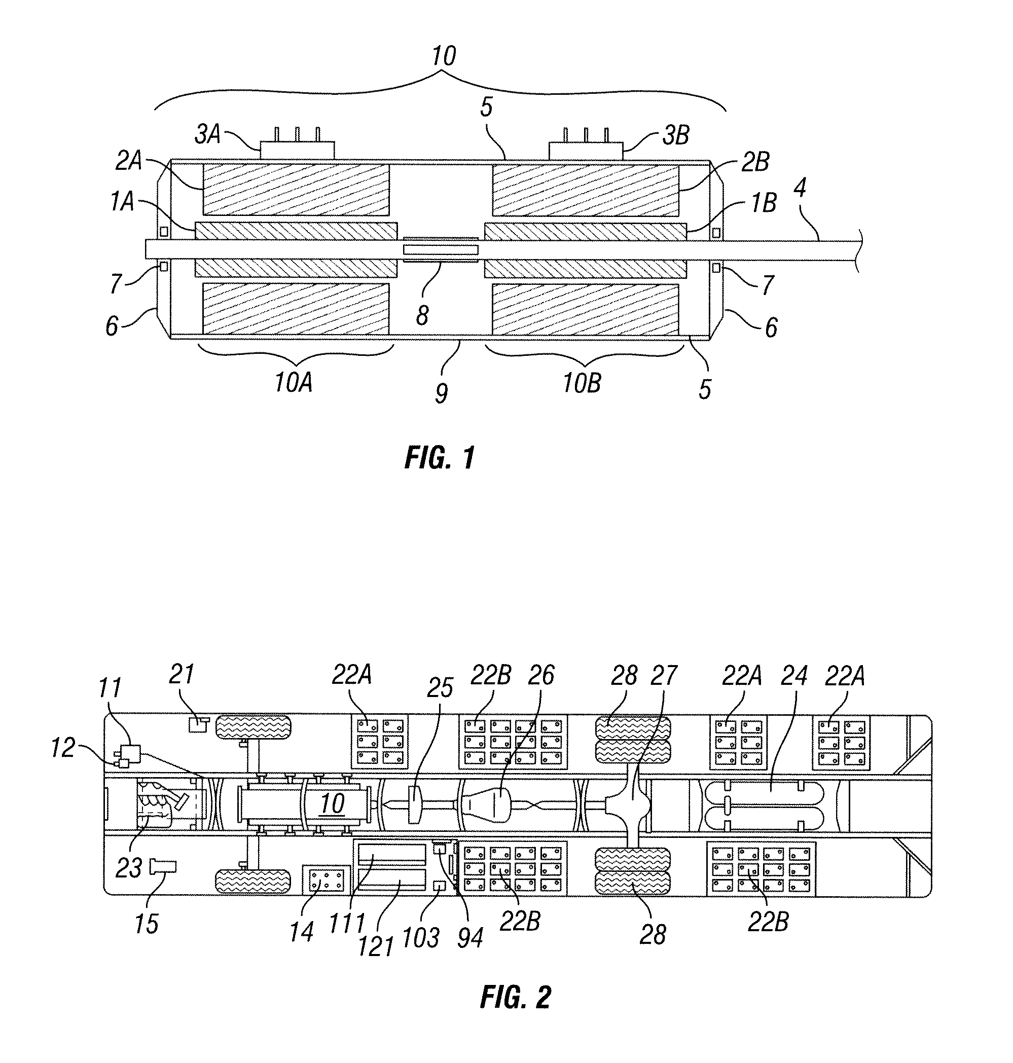
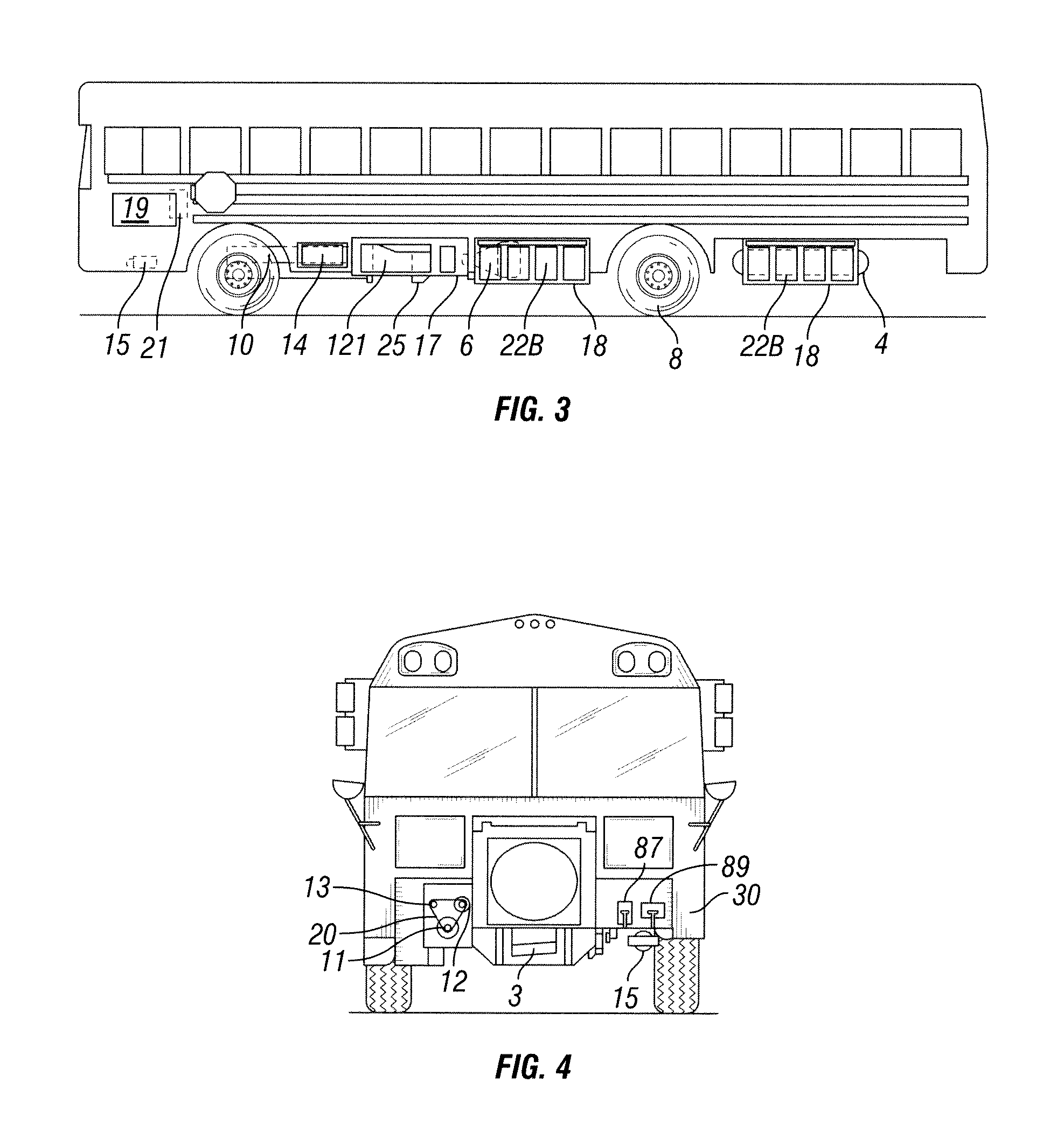
[0013]It is an object of this invention to present a novel vehicle configuration that satisfies the demands commonly placed on today's large public transportation vehicles. Examples of this invention introduce redundancy into an electric motor's construction. For example, the disability caused by a wire winding short is only 50% of the total power output of the motor. Additionally, examples of this invention utilize a multitude of smaller more economically accessible motor drive controllers, in a modular fashion, enabling cooperative operation of two motor units to act as one large electric traction motor.

Problems solved by technology

In some examples, these wire windings have been exposed to varnish vacuum pressure impregnation.

Method used


Image

  • Multiple Induction Electric Motor and Vehicle
  • Multiple Induction Electric Motor and Vehicle
  • Multiple Induction Electric Motor and Vehicle

Examples


Embodiment Construction

[0035]In at least one example embodiment of the invention, an electric motor is provided that produces higher output power at lower voltage levels than previous designs by mechanically coupling multiple smaller individual motor units along a common shaft inside one large motor housing. In one example, two individual motor units are joined by a common shaft. Each motor unit comprises a rotor-stator pair and variable frequency motor drive controller. The variable frequency motor drive controller provides a variable frequency alternating current to the exciter windings in the stator, setting up a rotating electromagnetic field about the exciter winding in the stator. This rotating magnetic field induces a current flow within a conductive element in the inductive rotor, which creates a magnetic field about that conductive element. The interaction of the rotating and induced magnetic fields results in the rotation of the rotor around the axis of the common shaft. It is this behavior in r...


PUM


Abstract

A novel multiple induction electric motor and vehicle that stores electrical power; provides a first and second direct current power input from the stored electrical power; separately produces first and second synchronized variable frequency alternating current control signal from the first and second direct current power inputs, respectively; produces first and second synchronized rotating magnetic fields responsive to the first and second variable frequency alternating current control signals, respectively; induces a first induced magnetic field around a conductor in a first inductive rotor responsive to the first rotating magnetic field; induces a second induced magnetic field around a conductor in a second inductive rotor responsive to the second rotating magnetic field; applies first and second rotational forces between the first and second rotating magnetic fields and the first and second induced magnetic fields to the shaft; and transmits the first and second rotational forces to a drive wheel.

Description

TECHNICAL FIELD[0001]The present invention relates generally to electric motors, and more specifically to induction motors as used in electrically powered vehicles.BACKGROUND[0002]Opposition to reliance on non-renewable sources of energy to power our transportation sector has been yearly growing stronger along with opposition to dependence on foreign supplies of energy. The United States has long relied on petroleum products to power its transportation. However, in the last 60 years, the U.S. has gone from being energy independent to relying 70% on foreign sources of energy. Alternatives are being sought that reduce our dependence on foreign petroleum based products out of environmental and security concerns. Vehicles fully or partially powered by electricity offer a solution to these concerns.[0003]A major hurdle in designing large electrically-powered road vehicles involves the traction motor. 3-phase alternating current induction motors are sturdy and reliable. They are capable o...

Claims


Application Information

Patent Timeline
IPC IPC(8): B60L11/02B60L11/18H02P27/04B60K1/00B60L50/10B60L50/12B60L50/15
CPCB60K1/00Y02T10/7088B60K1/04B60K15/07B60K2001/0438B60K2015/0638B60L1/003B60L3/0023B60L3/0046B60L3/0092B60L11/123B60L11/1877B60L2210/20B60L2220/20B60L2230/22B60L2230/24B60L2240/36B60L2250/16B60L2270/145B60Y2200/143B60Y2200/91Y02T10/6217Y02T10/7005Y02T10/705Y02T10/7077Y02T10/725Y02T90/12Y02T10/642Y02T10/641H02P5/69H02P27/00H02P27/04H02P6/04H02K16/02B60L2200/26Y02T10/70Y10S903/906B60K1/02B60L50/61B60L50/66B60L53/51B60L53/52B60L58/10Y02T10/62Y02T10/64Y02T10/7072Y02T10/72H02P9/02
Inventor ROSS, ROBERT
Owner MULTIPLE ELECTRIC SYST L L C
Learn More