
Secured system for fire suppression refill and recovery

a technology of secure system and fire suppression, applied in the field of secure system, can solve the problems of significant harm to both people and infrastructure, increased risks in sensitive locations, and security risks associated with the use of pressurized tanks, so as to prevent unauthorized access and operation, prevent tampering with the system, and improve safety and security

Inactive Publication Date: 2012-07-26
INT FIRE & SAFETY
View PDF13 Cites 9 Cited by
  • Summary
  • Abstract
  • Description
  • Claims
  • Application Information

AI Technical Summary

Benefits of technology

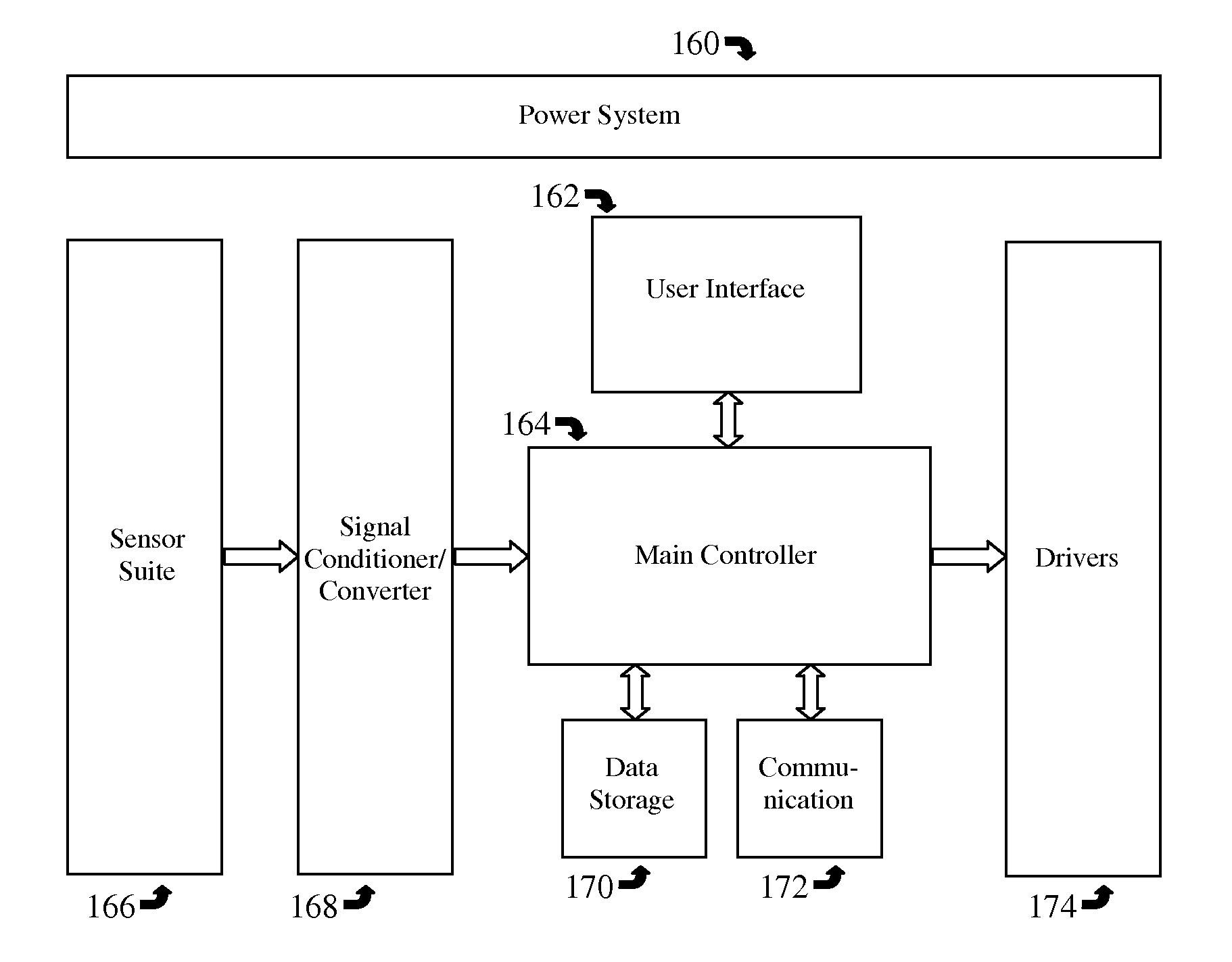
[0007]This invention encompasses an environmentally friendly secured system for fire suppression refill and recovery, and a method for making and using such a system. The invention improves safety and security of a fire suppression refill recovery system by preventing or minimizing both accidental and intentional hazards, preventing unauthorized access and operation of the system, providing for intensive traceable documentation and record keeping, and preventing tampering with the system. The invention minimizes or eliminates human error, ensures its proper operation with validation and documentation, and enhances accountability and forensic traceability while maintaining simplicity of operation.
[0025]The tank unit may include at least one tamper resistance measure designed to minimize the potential for the introduction of unauthorized material into the tank.
[0031]The tank unit may include fittings which constitute the pathway by which content enters and exits the tank. Fittings should be secured to prevent tampering. Fittings may be secured by way of a lock-out / tag-out protocol. In the case of a lock-out / tag-out protocol, all fittings and the tank should have integrated stubs with openings to facilitate the weaving of a tag wire. A breakable wire with a tag, preferably brightly colored, should be weaved through the openings in the stubs to tie and secure every linkage between a fitting and the tank, and between fittings. Termination of the tag wire should be performed with a traceable tool, such that the tool leaves unique identification information on the tag. The weaving method should be performed in one particular standard pattern so that a non-standard weaving pattern or a hasty weaving pattern may be an indication of tampering. Tampering may also be indicated by a broken or cut tag. When a deployed tank is used for extinguishing a fire, the action of pulling the hose will naturally break the tag. In this case, the tag should be replaced and the tank refilled and inspected. The disposal of a used tag in this case should be performed by a secure method to prevent counterfeiting of the tag.

Problems solved by technology

However, serious security and safety risks may be associated with the use of such pressurized tanks.
These risks are heightened in sensitive locations such as airports, military and other government installations, and chemical and ammunition storage sites.
Pressurized tanks can cause significant harm to both people and infrastructure when the tanks are deployed, used, or secured improperly.
The potential dangers associated with pressurized tanks include explosions and the expulsion of harmful material into the atmosphere surrounding the tanks.
Furthermore, pressurized tanks can become highly destructive weapons when filled with harmful biological or chemical agents.
A compromised tank, even when used inadvertently, has the potential to cause a catastrophic occurrence.
Prior to refill, a tank might be fitted with an unauthorized fitting, allowing for the introduction of an unauthorized agent into the tank at any time.
A tank might be lined or prefilled with a token amount of an unauthorized agent such that when an authorized agent is added, the tank content might become explosive, unstable, or harmful upon dispersal.
A structurally compromised tank, for example, a clone tank with a thin wall, might contain a harmful agent prior to being transported to the refill station.

Method used


Image

  • Secured system for fire suppression refill and recovery
  • Secured system for fire suppression refill and recovery
  • Secured system for fire suppression refill and recovery

Examples


Embodiment Construction

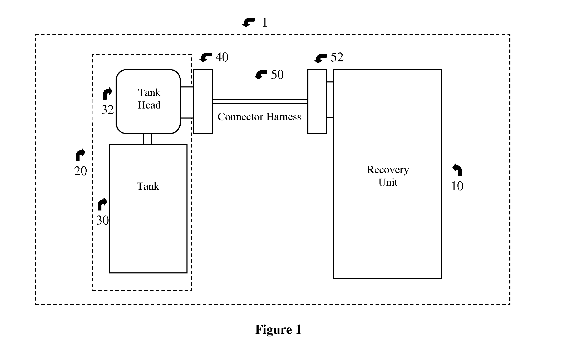
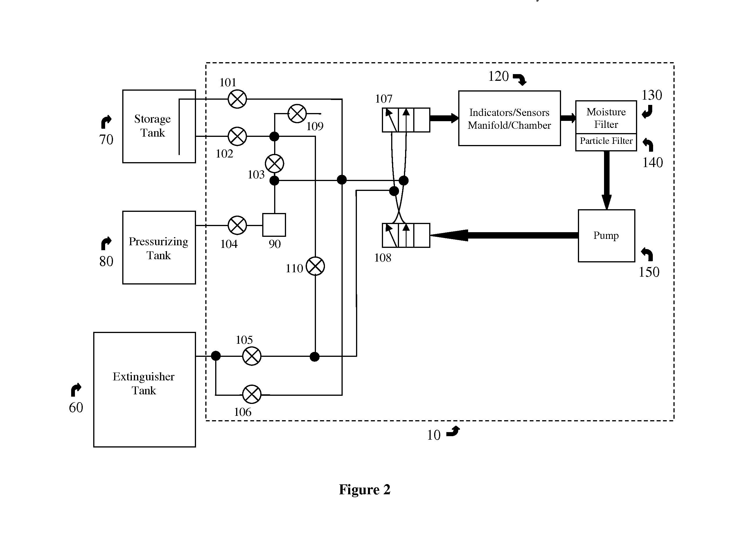
[0041]FIG. 1 shows a functional diagram of an embodiment of the secured system for fire suppression refill and recovery 1. The system 1 includes a recovery unit 10 and a tank unit 20. The recovery unit 10 contains the majority of the system components, including control electronics, valves, pump, sensors, power supply, and fittings 52 for the connector harness 50. The tank unit 20 consists of a tank 30 and a tank head 32 fitted tightly to the top portion of the tank 30. The connector harness 50 serves as the interface between the recovery unit 10 and the tank unit 20. The connector harness 50 includes hoses, cables, connectors and hose fittings. The tank unit 20 connects to the connector harness 50 via the tank hat 40. The tank hat 40 is a subsystem that is mounted onto the tank head 32. The tank hat 40 includes fittings for connection to the tank unit 20 via the tank head 32, a tank identifier such as an RFID or barcode scanner, an electro-mechanical relay circuit, indicators, and ...


PUM

PropertyMeasurementUnit
weightsaaaaaaaaaa
turbidityaaaaaaaaaa
pressureaaaaaaaaaa

Abstract

A secured system for fire suppression refill and recovery and a method for using such system. Operation of the system involves the refilling of an extinguisher tank with matter from a storage tank, the recovery of matter from an extinguisher tank to a storage tank, the cleansing of matter within a tank, and the purging of matter from a tank. The system includes a secure recovery unit, secure tank units, and equipment for connecting the recovery unit to the tank units. The system is configured such that, during its operation, safety and security risks commonly associated with the transfer of matter to and from extinguisher tanks are greatly reduced.

Description

BACKGROUND OF THE INVENTION[0001]This invention relates to a secure system for refilling and recovering the contents of pressurized fire extinguisher tanks.[0002]The purpose of a pressurized fire extinguisher tank is to enable its user to suppress a fire from a safe distance. However, serious security and safety risks may be associated with the use of such pressurized tanks. These risks are heightened in sensitive locations such as airports, military and other government installations, and chemical and ammunition storage sites.[0003]Pressurized tanks can cause significant harm to both people and infrastructure when the tanks are deployed, used, or secured improperly. The potential dangers associated with pressurized tanks include explosions and the expulsion of harmful material into the atmosphere surrounding the tanks. Furthermore, pressurized tanks can become highly destructive weapons when filled with harmful biological or chemical agents. A compromised tank, even when used inadv...

Claims


Application Information

Patent Timeline
Patent Type & Authority Applications(United States)
IPC IPC(8): B67C3/00B65D85/00
CPCA62C35/15
Inventor BRIDGES, GEORGE A.BRIDGES, PAMELA SUE
Owner INT FIRE & SAFETY
Learn More