Rack and manufacturing method thereof
a manufacturing method and rack technology, applied in the field of manufacturing methods, can solve the problems of difficult to maintain the increase production costs, and high cost of the dies that press the rack, and achieve the effects of securing the width dimension, strength and rigidity of the rack teeth, and low cos
- Summary
- Abstract
- Description
- Claims
- Application Information
AI Technical Summary
Benefits of technology
Problems solved by technology
Method used
Image
Examples
first embodiment
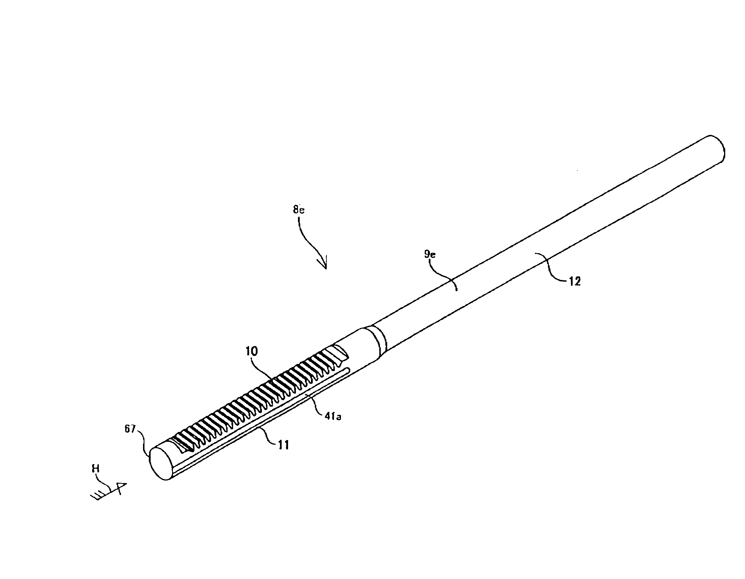
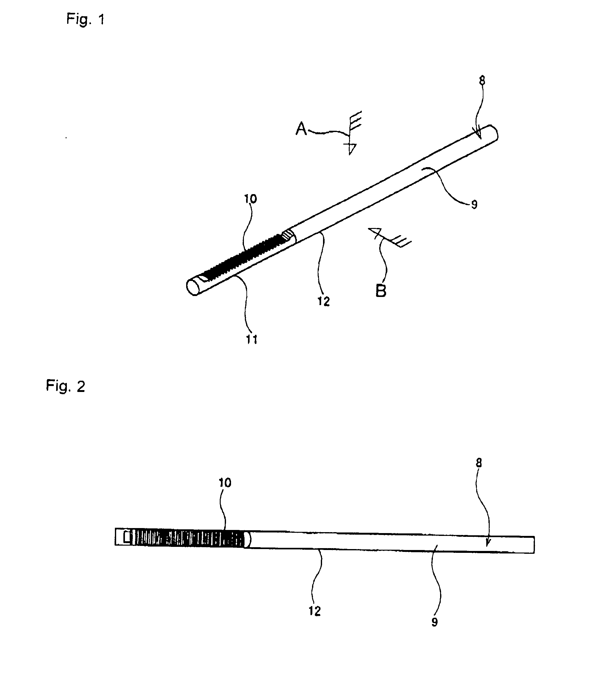
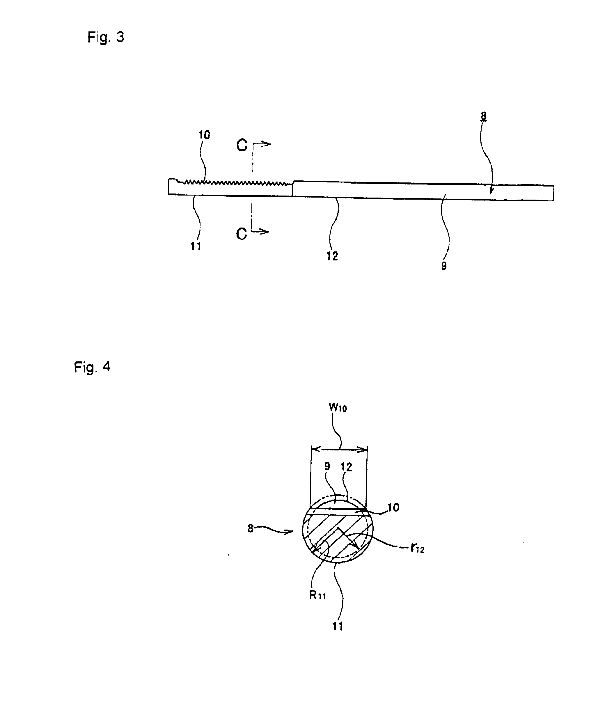
[0153]FIGS. 1 to 8 show a first embodiment of the present invention. First, the construction of the rack 8 of this embodiment will be explained based on FIGS. 1 to 4. In the explanation below, the radius of curvature of each surface, unless specified otherwise, is taken to be the radius of curvature of the cross sectional shape of each surface.
[0154]The rack 8 is made of a metal material such as carbon steel, stainless steel or the like, and comprises a rod unit 9 that is a solid material having a circular cross section, and rack teeth 10 that are formed by plastic working on one side surface in the radial direction of part in the axial direction (left part in FIGS. 1 to 3) of the rod unit 9. In this embodiment, the rod unit 9 is made from a single metal material that is the same over the entire length from the outer surface to the center. Moreover, in the part in the axial direction of this rod unit 9, the radius of curvature R11 (see FIG. 4) of the cross sectional shape of the rea...
second embodiment
[0166]FIG. 10 and FIG. 11 show a second embodiment of the present invention. In this embodiment, the amount of processing in the upsetting work shown in (A) to (B) of FIG. 10 is greater than that in the case of the first embodiment described above, and the width dimension of the intermediate material 20a that is obtained in this upsetting work is larger than in the case of the first embodiment. In addition, the radius of curvature of the partial cylindrical surface portion 17a is greater than in the case of the first embodiment.
[0167]In this embodiment, as shown in (C) to (D) of FIG. 10, the intermediate material 20a as described above, is pressed into a retaining hole 22 of a die 21 while plastically deforming both end portions in the width direction. This die 21 is the same as that used in the first embodiment. However, since the amount that the width dimension of the intermediate material 20a is larger, when pressing the intermediate material 20a into the retaining hole 22, both ...
third embodiment
[0170]FIG. 12 shows a third embodiment of the present invention. In the case of this embodiment, as shown in (A) to (B) of FIG. 12, by performing an ironing work on a material 13 by passing it through a die 36, the outer diameter of this material 13 is reduced except for part in the axial direction. Moreover, the result is taken to be a preliminary intermediate material 37 having a portion in the axial direction whose outer diameter is greater than the outer diameter of the remaining portion in the axial direction, and of this preliminary intermediate material 37, the portion in the axial direction having the larger diameter is plastically deformed in the same manner as in the first embodiment or in the second embodiment described above to obtain a rack 8a as shown in (C) of FIG. 12. In the case of this kind of embodiment, it is possible to reduce the diameter of the portion of the rack 8a that is separated in the axial direction from the portion where the rack teeth 10 are formed, ...
PUM
| Property | Measurement | Unit |
|---|---|---|
| radius of curvature | aaaaa | aaaaa |
| shape | aaaaa | aaaaa |
| outer diameter | aaaaa | aaaaa |
Abstract
Description
Claims
Application Information
 - R&D
- Intellectual Property
- Life Sciences
- Materials
- Tech Scout
- Unparalleled Data Quality
- Higher Quality Content
- 60% Fewer Hallucinations
Browse by: Latest US Patents, China's latest patents, Technical Efficacy Thesaurus, Application Domain, Technology Topic, Popular Technical Reports.
© 2025 PatSnap. All rights reserved.Legal|Privacy policy|Modern Slavery Act Transparency Statement|Sitemap|About US| Contact US: help@patsnap.com


