
Method for producing alkaline primary battery

a technology of primary batteries and alkali, which is applied in the direction of cell components, cell component details, electrochemical generators, etc., can solve the problems of difficult suppression of internal short circuit, and deterioration of battery performance, so as to achieve the effect of not increasing the internal resistance of the battery and suppressing the lower end of the cylindrical portion of the separator

Active Publication Date: 2012-07-26
PANASONIC CORP
View PDF3 Cites 3 Cited by
  • Summary
  • Abstract
  • Description
  • Claims
  • Application Information

AI Technical Summary

Benefits of technology

[0017]In Patent Document 3, inward bending of the cylindrical portion of the separator is reduced. However, since the separator has two bottom portions, the total thickness of the bottom portions of the separator increases. Thus, the amount of the negative electrode filled therein (negative electrode capacity) decreases and the internal resistance of the battery increases, thereby resulting in deterioration of battery performance.
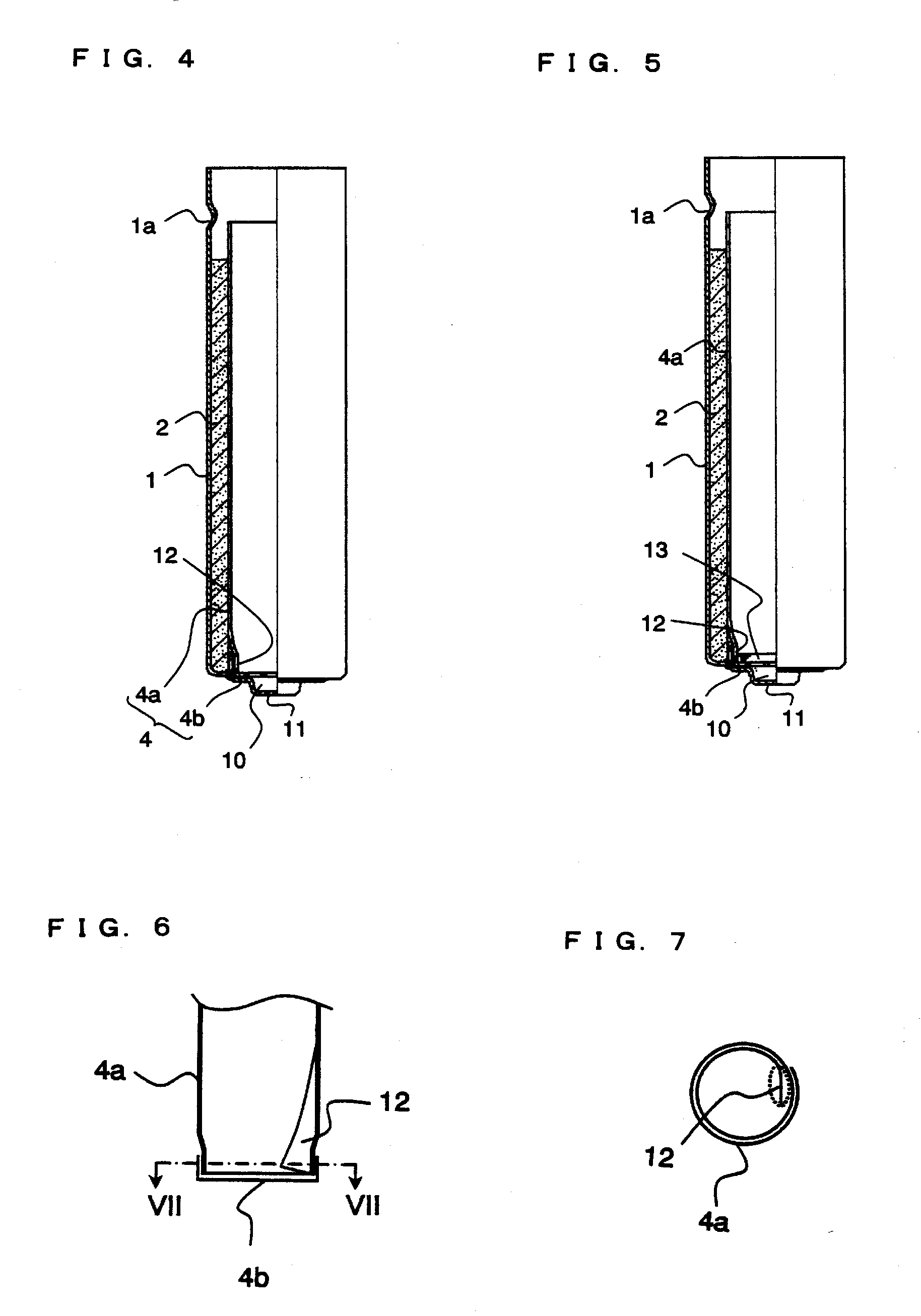
[0027]According to the invention, when the gelled negative electrode is filled into the separator, the lower end of the cylindrical portion of the separator is in contact with the upstanding portion of the bottom portion while being immersed in the electrolyte remaining in the separator. Therefore, the gelled negative electrode of predetermined amount is prevented from overflowing from the separator and is contained in the separator.

Problems solved by technology

As a result, the negative electrode overflows from the separator, thereby coming into contact with the positive electrode to cause an internal short circuit.
Thus, the amount of the negative electrode filled therein (negative electrode capacity) decreases and the internal resistance of the battery increases, thereby resulting in deterioration of battery performance.
Therefore, according to the technique of using two bottom portions of a separator, it is difficult to suppress deterioration of battery performance while suppressing inward bending of the lower end of the cylindrical portion of the separator.

Method used


Image

  • Method for producing alkaline primary battery
  • Method for producing alkaline primary battery
  • Method for producing alkaline primary battery

Examples


example 1

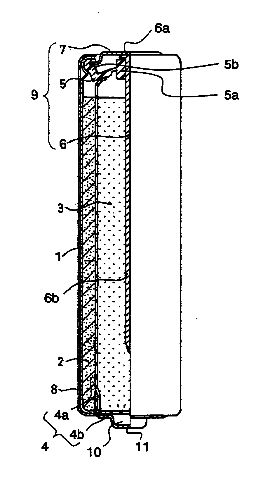
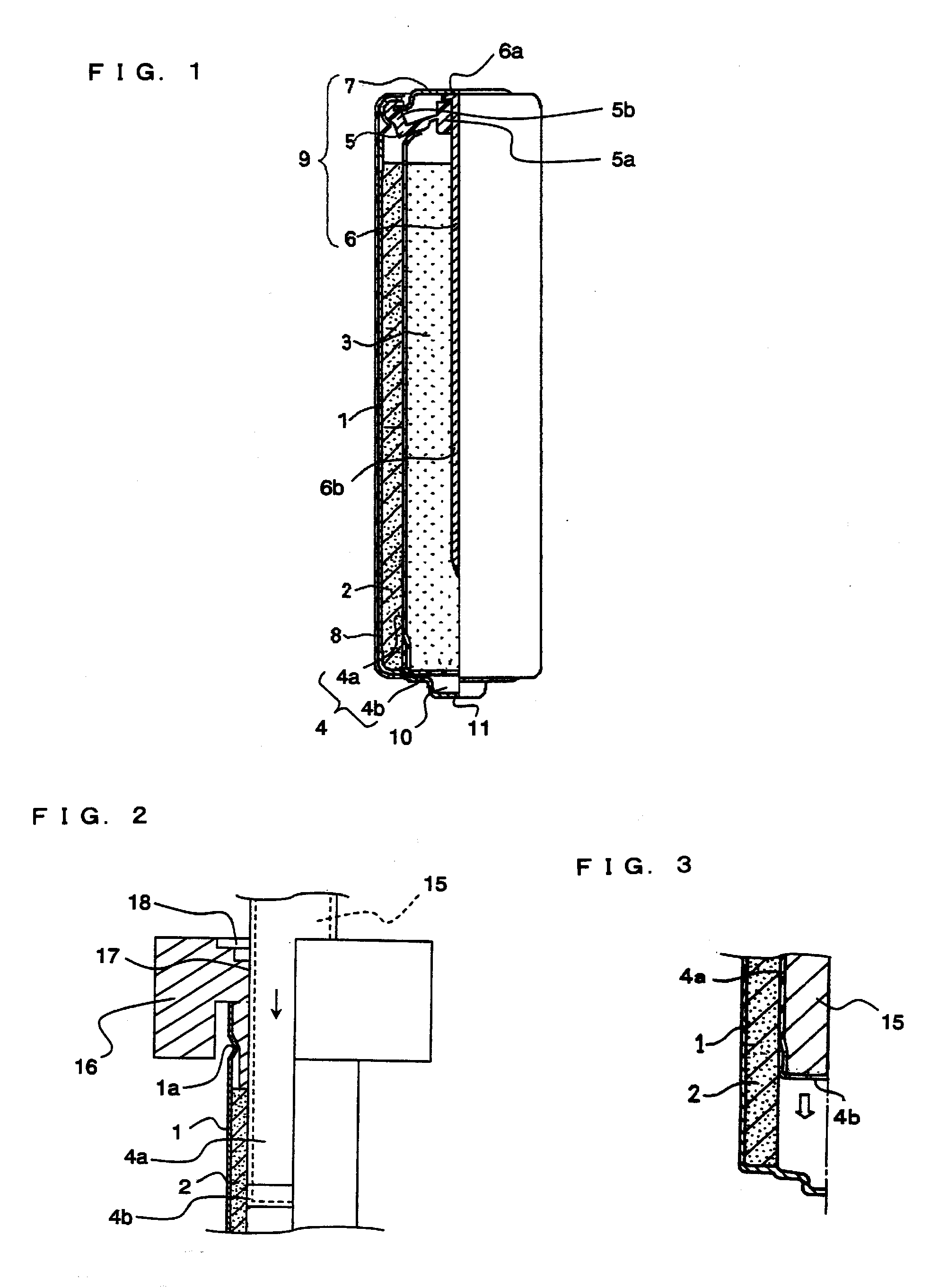
[0116]A battery with the structure illustrated in FIG. 1 was produced in the following manner.

[Step (1)]

[0117]An electrolytic manganese dioxide powder (Tosoh Corporation, HHTF, mean particle size 35 μm) serving as a positive electrode active material and a graphite powder (Nippon Graphite Industries, Ltd., SP-20, mean particle size 10 μm) serving as a conductive agent were mixed in a weight ratio of 95:5. This mixture was mixed with an electrolyte in a weight ratio of 100:2, sufficiently stirred, and pressed into flakes. The electrolyte used was an aqueous solution containing potassium hydroxide (KOH concentration: 35% by weight) and zinc oxide (ZnO concentration: 2% by weight). The flakes of the positive electrode mixture were crushed into granules, which were then classified with a sieve. The granules of 10 to 100 mesh were compression molded into the shape of a hollow cylinder, to obtain positive electrode pellets 2a (outer diameter 13.55 mm, internal diameter 9.15 mm, height 22 ...


PUM

PropertyMeasurementUnit
weight M2aaaaaaaaaa
weight M2aaaaaaaaaa
granule sizeaaaaaaaaaa

Abstract

A method for producing an alkaline primary battery includes: (1) forming a cylindrical positive electrode having a hollow; (2) inserting a cylindrical separator with a bottom into the hollow of the positive electrode, the separator including: a wound cylindrical portion; and a bottom portion that is substantially U-shaped in cross-section, the bottom portion covering an opening of the cylindrical portion at a lower end thereof and having an upstanding portion that extends along a lower outer face of the cylindrical portion; and (3) injecting an electrolyte into the separator. The amount of the electrolyte injected into the separator in the step (3) is sufficient to impregnate the positive electrode and the separator and immerse a lower end of the cylindrical portion of the separator in the electrolyte remaining in the separator, thereby bringing the lower end of the cylindrical portion into contact with the upstanding portion.

Description

FIELD OF THE INVENTION[0001]This invention relates to methods for producing alkaline primary batteries, and more particularly to an improvement in the step of injecting an electrolyte into a battery case in a method for producing an alkaline primary battery (hereinafter may also be referred to as an “alkaline battery”).BACKGROUND OF THE INVENTION[0002]A typical method for producing an alkaline battery includes the steps of:[0003](A) inserting at least one positive electrode pellet into a cylindrical battery case with a bottom and pressing the positive electrode pellet to form a cylindrical positive electrode having a hollow and adhering closely to an inner face of the battery case;[0004](B) inserting a cylindrical separator with a bottom into the hollow of the positive electrode inside the battery case;[0005](C) injecting an electrolyte into the separator to impregnate the positive electrode and the separator with the electrolyte;[0006](D) filling a gelled negative electrode into th...

Claims


Application Information

Patent Timeline
Patent Type & Authority Applications(United States)
IPC IPC(8): H01M6/02H01M50/107H01M50/414
CPCH01M2/0237H01M2/162H01M4/08H01M4/625H01M6/045Y10T29/49112Y10T29/49108Y10T29/49114Y10T29/4911Y10T29/49115H01M6/085H01M50/44H01M50/414H01M50/107
Inventor ADACHI, MITSUJISYOJI, YASUHIKO
Owner PANASONIC CORP
Learn More