Network jack
a network jack and jack technology, applied in the direction of coupling devices, two-part coupling devices, electrical devices, etc., can solve the problems of design not being able to solve vibrations yet, and still exist quite large gaps between the door and the housing, and achieve good stability
- Summary
- Abstract
- Description
- Claims
- Application Information
AI Technical Summary
Benefits of technology
Problems solved by technology
Method used
Image

Examples
embodiment 1
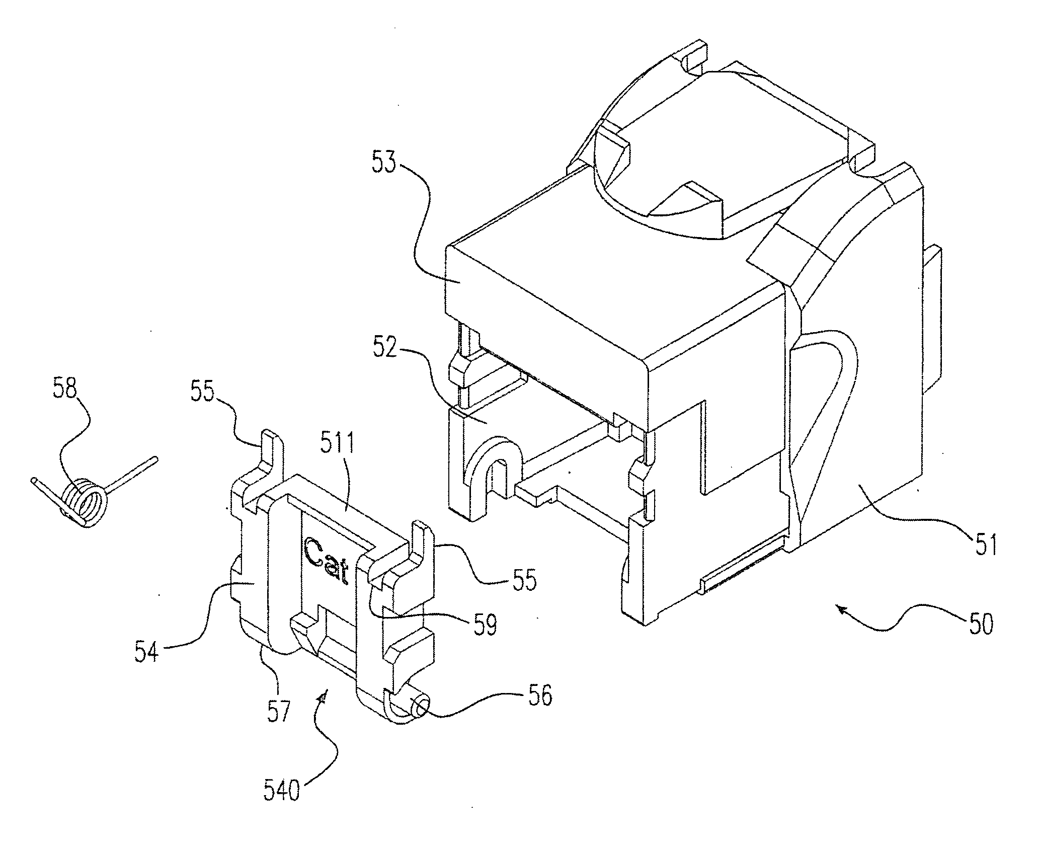
[0037] a network jack includes a jack body having an opening and a side wall; a door body having a lateral protrusion; and a resilient pivot connecting the jack body and the door body and urging the lateral protrusion against the side wall.
[0038]Embodiment 2: the network jack. according to embodiment 1, the door body has an edge, the side wall has an inner wall contacting the lateral protrusion, the lateral protrusion is a pillar protruding from the edge, the resilient pivot is disposed on the door body and includes a spring with a first end and a second end, the door body has a spring shelter protecting the spring and has a slot and a recess, and the first and the second ends are respectively contained in the slot and the recess to prevent from being interfered with each other.
[0039]Embodiment 3: the network jack according to embodiment 1, the door body has a first stabilizer being a groove, the jack body has a second stabilizer being a tenon and the first stabilizer is operated to...
embodiment 4
[0040] a plate element for closing an opening having a diagonal length of a network jack includes a door body having a height and configured to close the opening of the network jack; and a lateral protrusion extending from the door body and having a length, wherein a sum of the height and the length is larger than the diagonal length.
[0041]Embodiment 5: the plate element according to embodiment 4 further includes a spring having a first end and a second end and configured on the door body.
[0042]Embodiment 6: the plate element according to embodiment 4, the lateral protrusion is a flexible plate, the door body has a slot and a recess, and the first and the second ends are respectively contained in the slot and the recess.
embodiment 7
[0043] a plate element for closing an opening having a first characteristic length of a network jack includes a door body having a second characteristic length and configured to close the opening of the network jack; and a lateral protrusion extended from the door body and having a third characteristic length, wherein a sum of the second and the third characteristic lengths is larger than the first characteristic length.
[0044]Embodiment 8: the plate element according to embodiment 7, the first characteristic length is one of a width and a diagonal length of the opening, the second characteristic length is a height of the door body and the third characteristic length is an extension length of the lateral protrusion.
[0045]Embodiment 9: the plate element according to embodiment 7, the lateral protrusion is extended from one being selected from a group consisting of places in a width direction, a height direction and a corner direction of the door body.
PUM
 Abstract
Description
Claims
Application Information
 - R&D
- Intellectual Property
- Life Sciences
- Materials
- Tech Scout
- Unparalleled Data Quality
- Higher Quality Content
- 60% Fewer Hallucinations
Browse by: Latest US Patents, China's latest patents, Technical Efficacy Thesaurus, Application Domain, Technology Topic, Popular Technical Reports.
© 2025 PatSnap. All rights reserved.Legal|Privacy policy|Modern Slavery Act Transparency Statement|Sitemap|About US| Contact US: help@patsnap.com