
Manufacturing Apparatus And Method Of Forming A Preform

a technology of manufacturing apparatus and preform, which is applied in the direction of preformed elements, pipes, moulds, etc., can solve the problems that the composition used to produce the preform does not meet the strength requirements of the final preform, and achieve the effects of convenient integration or mixing, convenient process, and easy formation

Active Publication Date: 2012-07-19
ROYAL BANK OF CANADA
View PDF12 Cites 3 Cited by
  • Summary
  • Abstract
  • Description
  • Claims
  • Application Information

AI Technical Summary

Benefits of technology

[0011]Therefore, the present invention provides for the manufacturing apparatus that allows for an automated production of the preforms thus providing a more efficient process. Wrapping the layers on top of each other provides for the preform to be easily formed of a desired thickness. Additionally, the layers are easily integrated or blended together when the layers are disposed on top of each other. Further, the second end provides one small seam to be integrated or blended into the respective layer. Also, the preform as described herein is easily removable from the mandrel without being damaged and is resistant to cracking.

Problems solved by technology

More specifically, the composition used to produce the preform does not meet the strength requirements for the final preform.

Method used


Image

  • Manufacturing Apparatus And Method Of Forming A Preform
  • Manufacturing Apparatus And Method Of Forming A Preform
  • Manufacturing Apparatus And Method Of Forming A Preform

Examples


Embodiment Construction

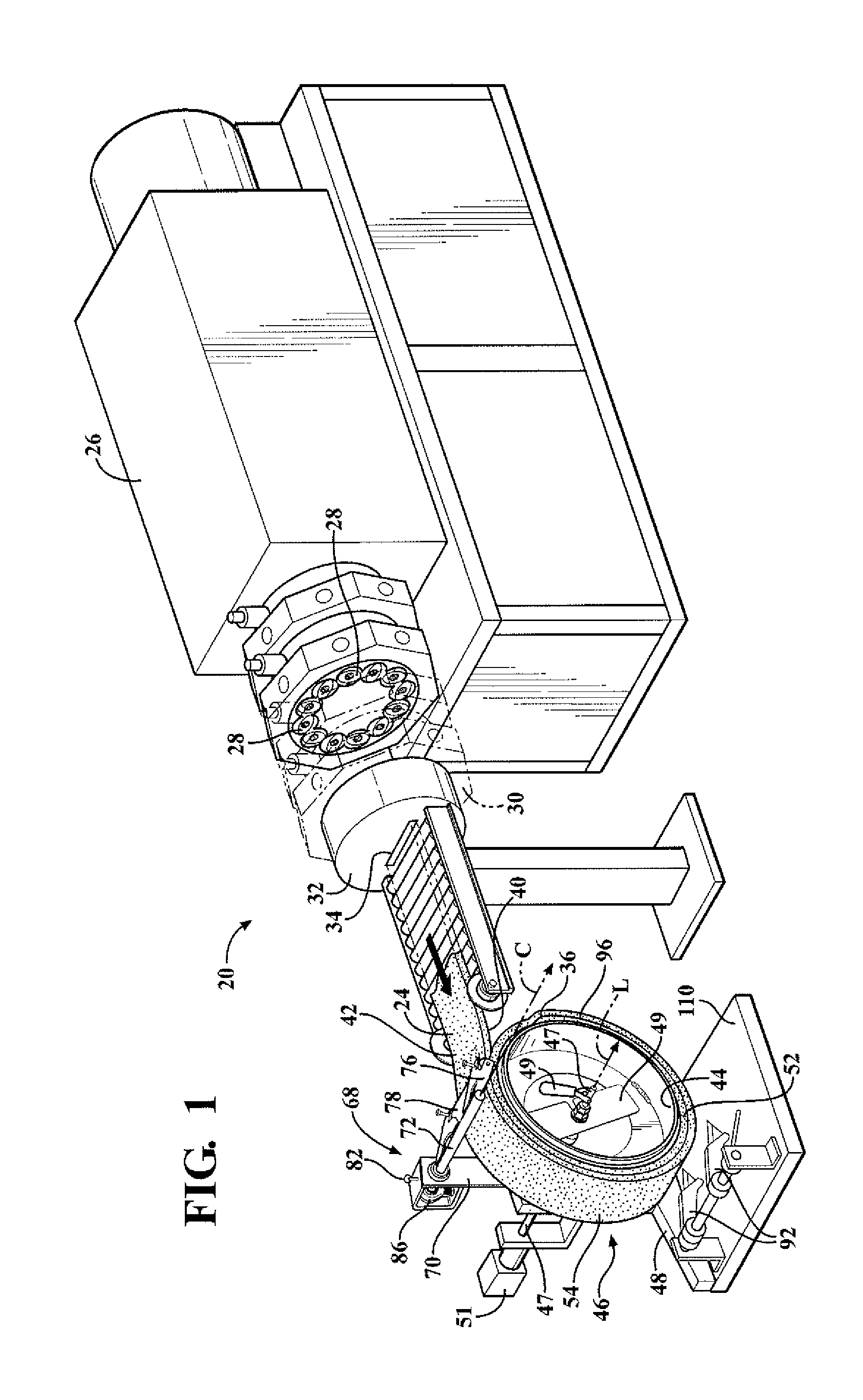
[0025]Referring to the Figures, wherein like numerals indicate like or corresponding parts throughout the several views, a manufacturing apparatus 20 for forming a ceramic article or preform 22 from an extrudate 24 is generally shown in FIG. 1. More specifically, the manufacturing apparatus 20 is utilized for forming a ceramic preform 22 from the extrudate 24.

[0026]The manufacturing apparatus 20 includes a multi-screw extruder 26 for processing a composition for forming the extrudate 24. In other words, the composition is mixed in the multi-screw extruder 26 for forming the extrudate 24. The composition generally comprises ceramic particles and ceramic fibers having an aspect ratio of greater than or equal to 10:1. The ceramic fibers are substantially randomly orientated in three dimensions. It is to be appreciated that the composition can be manufactured from materials other than ceramic particles and ceramic fibers. The composition will be discussed further below.

[0027]The multi-s...


PUM

PropertyMeasurementUnit
Angleaaaaaaaaaa
Angleaaaaaaaaaa
Angleaaaaaaaaaa

Abstract

The present invention provides for a manufacturing apparatus for forming a ceramic preform from an extrudate having a first end and a second end. A cutter forms the first and second ends of the extrudate complementary to each other such that the first and second ends of the extrudate align with each other in a spaced relationship to define a preform having a substantially uniform exterior surface and a substantially uniform thickness. The present invention provides for a method of forming the preform from the extrudate having the first and second ends utilizing a mandrel. The method includes the step of aligning the second end complementary to the first end of the first layer in a spaced relationship to define the preform having the substantially uniform exterior surface and the substantially uniform thickness.

Description

CROSS REFERENCE TO RELATED APPLICATION[0001]This application claims the benefit of U.S. Provisional Patent Application Ser. No. 61 / 396,596, filed on May 28, 2010, the disclosure of which is hereby incorporated by reference in its entirety.STATEMENT REGARDING FEDERALLY SPONSORED RESEARCH OR DEVELOPMENT[0002]The U.S. Government has a paid-up license in this invention and the right in limited circumstances to require the patent owner to license others on reasonable terms as provided for by the terms of Contract Nos. W56 HZV-05-C-0760 and ______ awarded by the U.S. Army Tank & Automotive Command (TACOM).BACKGROUND OF THE INVENTION[0003]1. Field of the Invention[0004]The present invention relates to a manufacturing apparatus and a method of forming a preform.[0005]2. Description of the Related Art[0006]Manufacturing preforms, such as ceramic preforms, are known in industry. However, current methods for manufacturing ceramic preforms are accomplished through a manual batch mixing process ...

Claims


Application Information

Patent Timeline
IPC IPC(8): B32B1/08B32B18/00G03D15/04B29C47/06C04B35/64B29C48/07B29C48/08B29C48/09
CPCB28B1/42Y10T428/1314B32B18/00C04B35/117C04B35/563C04B35/565C04B35/6316C04B35/6365C04B35/803C04B35/806C04B2235/3418C04B2235/5228C04B2235/5248C04B2235/5268C04B2235/5296C04B2235/6021C04B2235/77C04B2237/343C04B2237/36C04B2237/365C04B2237/38B29C47/0019B29C47/0021B29C47/0064C04B2235/6567C04B2237/84B28B21/48B29C48/09B29C48/0019B29C48/0021B29C48/022B29C48/0022B29C48/07B29C48/08C04B35/80C04B35/64C04B35/62625C04B35/6224C04B35/76C04B35/10B29K2909/02B29K2105/06B29K2105/12B28B21/42B28B21/22B28B21/24B28B21/242B28B21/52B28B21/78B28B21/72
Inventor ANDERSON, NEILKERO, MATT
Owner ROYAL BANK OF CANADA
Learn More