System and Method for Termination Powered Differential Interface Periphery

a technology of differential interface and system, applied in the field of peripheral device powering, can solve the problems of current dissipation, dc current and consumption power, and a large amount of power consumption, and achieve the effect of reducing power consumption, reducing power consumption, and reducing power consumption

Active Publication Date: 2012-07-19
ANALOGIX SEMICON
View PDF2 Cites 3 Cited by
  • Summary
  • Abstract
  • Description
  • Claims
  • Application Information

AI Technical Summary

Problems solved by technology

Since the drivers are differential, they draw a constant DC current and consume power.
This part of the power is typically wasted.
This power is currently dissipated in setting up the DC conditions of the drivers and hence wasted.

Method used


Image

  • System and Method for Termination Powered Differential Interface Periphery
  • System and Method for Termination Powered Differential Interface Periphery
  • System and Method for Termination Powered Differential Interface Periphery

Examples


Embodiment Construction

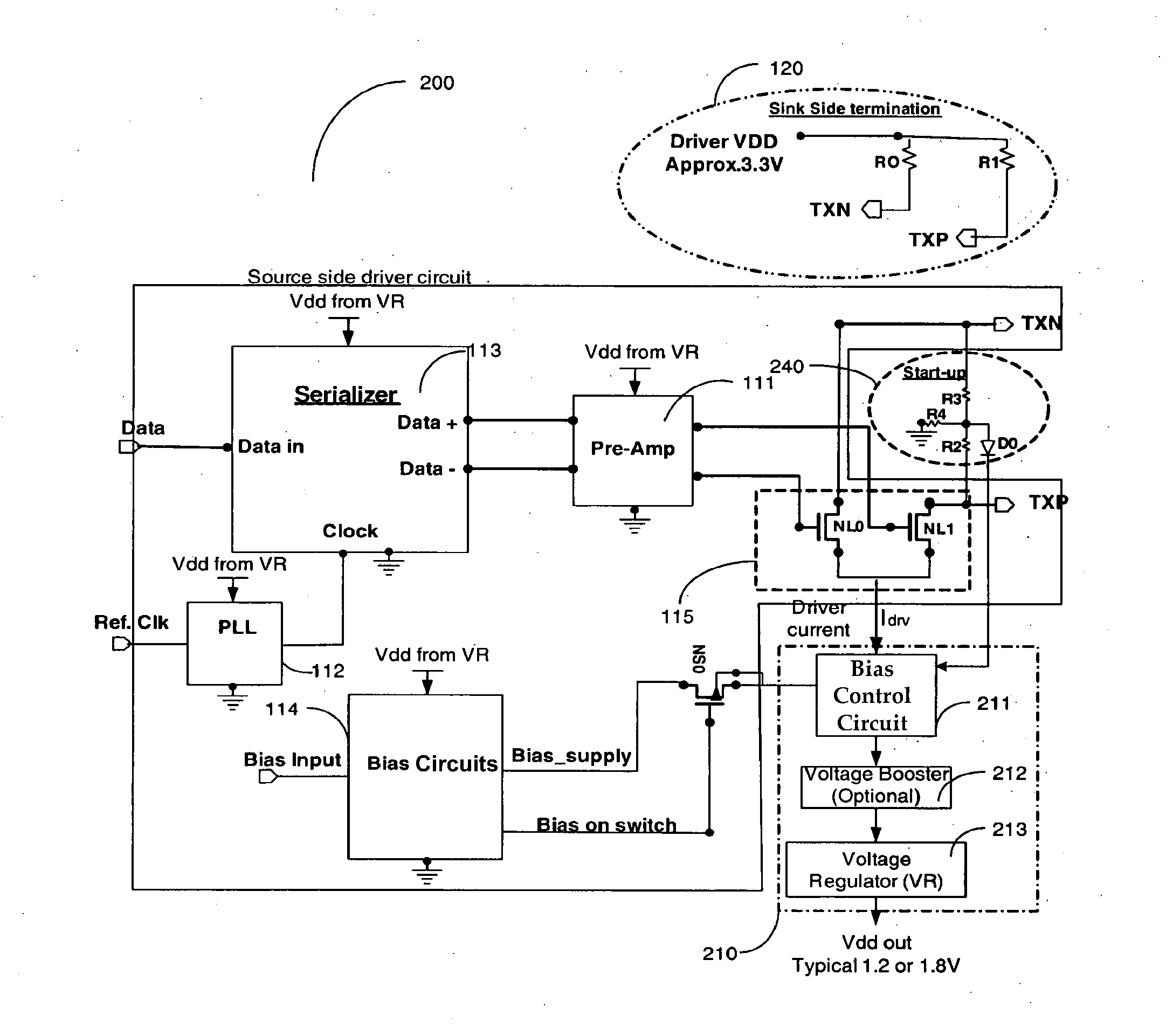
[0012]An apparatus and method for supplying power to the peripheral circuits of a transmitter circuit, especially a high-definition multimedia interface (HDMI) transmitter circuit, is disclosed. In an HDMI transmitter, the termination resistors of the output driver are part of the receiver. DC power for the driver is supplied through these termination resistors. In prior art implementations, power supplied by the receiver circuit is wasted in setting the DC conditions of the differential line driver. It is suggested to use this wasted power from the remote termination to power selected peripheral circuits of the transmitter. The use of this wasted power of the line driver for powering the peripheral circuits reduces the total system power.

[0013]FIG. 2 is a non-limiting and exemplary HDMI video system 200 using the disclosed invention. The output drivers have sink side termination 120, including resistors R0 and R1, at the receiver, connected to the receiver's power supply. In a typi...


PUM


Abstract

An apparatus and method for supplying power to the peripheral circuits of a transmitter circuit, especially an HDMI transmitter circuit, is disclosed. In an HDMI transmitter, the termination resistors of the output driver are part of the receiver. DC power for the driver is supplied through these termination resistors. In prior art implementations, power supplied by the receiver circuit is wasted in the DC set-up circuit of the differential line driver. In various embodiments, this wasted power may be recovered from the remote termination to power selected peripheral circuits of the transmitter. The use of this wasted power may reduce the total system power consumption.

Description

CROSS-REFERENCE TO RELATED APPLICATIONS[0001]This application is a continuation of U.S. patent application Ser. No. 11 / 800,861, filed on May 7, 2007, which is incorporated herein by reference.BACKGROUND OF THE INVENTION[0002]1. Field of the Invention[0003]The invention generally relates to the powering of peripheral devices through a remotely terminated differential driver load supply and more specifically to powering of peripheral circuits of an HDMI transmitter from the wasted power of the HDMI transmitter driver that is terminated at the receiver.[0004]2. Prior Art[0005]A typical high-definition multimedia interface (HDMI) transmission system 100 is shown in FIG. 1. The HDMI system has a source side driver 110 at the transmitter, with the drivers and the peripheral circuits, and a sink side termination 120 at the receiver. The twin differential drivers NL0 and NL1 of the source transmitter 115, driving the signal lines TXN and TXP respectively, are terminated through the terminat...

Claims


Application Information

Patent Timeline
Patent Type & Authority Applications(United States)
IPC IPC(8): H04N5/38
CPCH03K19/0008H04L25/028H04L25/0272H04L25/0264
Inventor CHI, HONGWU
Owner ANALOGIX SEMICON
Why Eureka
Try Eureka