Eureka AIR delivers breakthrough ideas for toughest innovation challenges, trusted by R&D personnel around the world.

Light guiding system and a method for controlling the same

a technology of light guiding system and light guiding method, which is applied in emergency power supply arrangements, lighting and heating apparatus, instruments, etc., can solve the problems of shortening the illumination time period, and achieve the effect of improving orientation

Active Publication Date: 2012-07-19
SIGNIFY HLDG BV
View PDF11 Cites 28 Cited by
  • Summary
  • Abstract
  • Description
  • Claims
  • Application Information

AI Technical Summary

Benefits of technology

[0004]It is therefore an object of the present invention to provide an economic and reliable light guidance system, wherein an illumination of a person's surroundings is adapted to the requirements of the situation, thus improving orientation.
[0010]In another example, in case of a high-charged auxiliary power supply system and a presence signal, the light level is increased for a predetermined time period. Thus, the surroundings are well illuminated for a person passing by, if there is enough power available. The predetermined time period may be an estimation of an average time interval for traversing the illuminated area and approaching the next light unit. It may also be required to maintain the high-level illumination longer in order to make a passing person feeling comfortable and safe.
[0013]In another example, the control unit is adapted to adjust the light level of the light unit and to adjust a lighting period in dependency of the power value of the auxiliary power supply system. Therefore, not only the intensity level of illumination is adapted to the available power, but also the time interval, for which a higher intensity level is maintained, in order to meet ensuring regulations. For instance, the light level as well as the period for maintaining this light level may be continuously adjustable. Thereby, the performance required by the presence of a person is balanced versus the given condition of the power value and the needs can be encountered in an optimized fashion. To further save energy, the light unit may be controlled to switch repeatedly between a high intensity level and a low intensity level with a relatively high predetermined frequency, provided that the norms allow such switching. This blinking mode will reduce the consumed power and thus lengthen a possible illumination period.
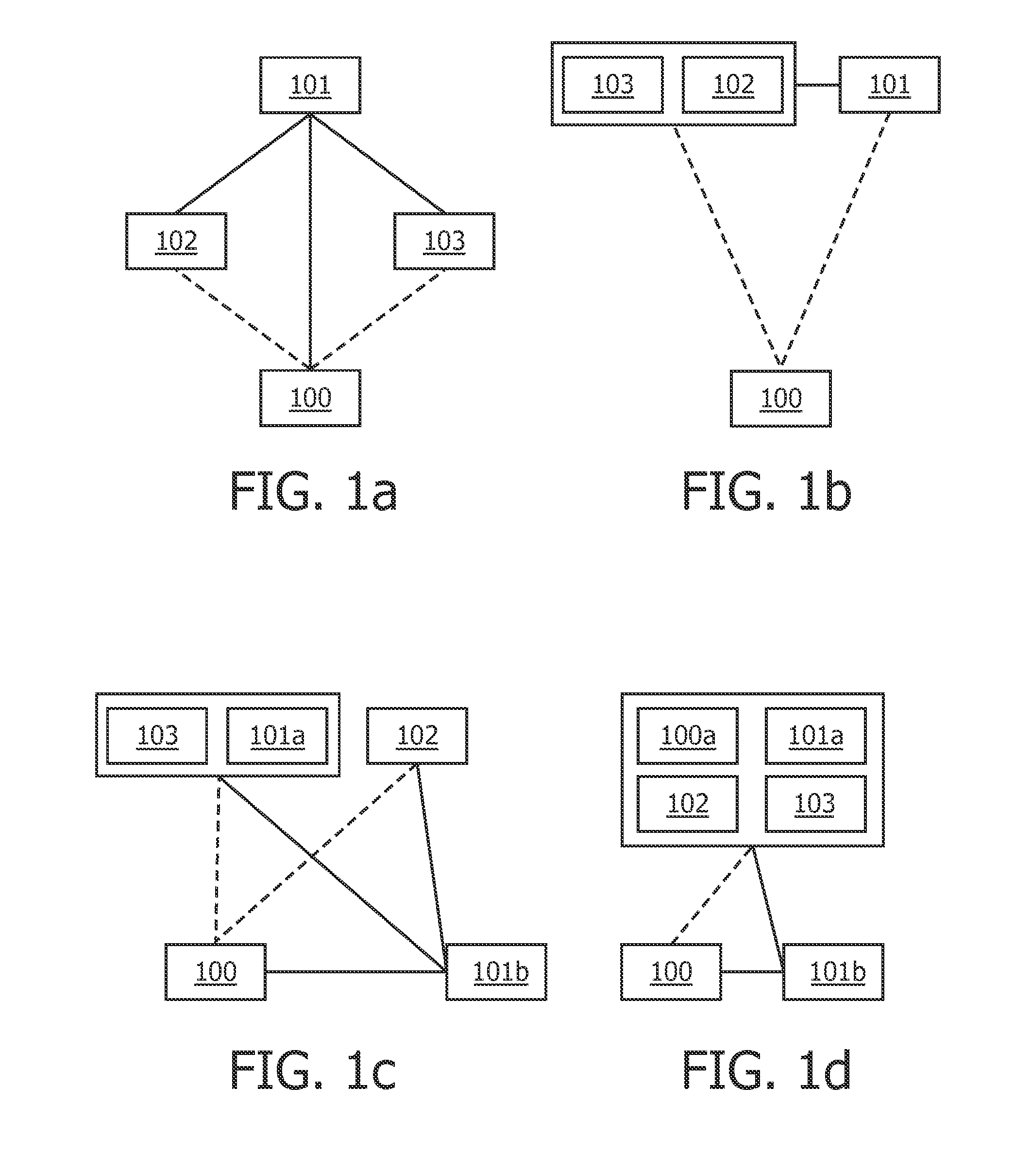
[0016]Preferably, a light guidance system according to an embodiment of the present invention also comprises at least one presence sensor or a presence sensor array adapted to detect the presence of a person and, in case of presence detection, to provide the presence signal to the control unit. By only transmitting a presence signal to the control unit in case of a person being detected, unnecessary information and network flooding is avoided. This is of particular importance, if low data-rate networks are used for data transmission. The signals may be sent via a wired or wireless network or a combination of both. Preferably, each light unit may be provided with its own presence sensor, so that the assignment of the presence signal to a particular light unit may already be determined by the sending presence signal. For this, the presence signal may contain an identification code of the presence sensor or of the light unit. Alternatively, a presence sensor is assigned to several light units and the closest light unit has to be determined by estimating a distance of a person to each light unit. In this case, the presence signal may comprise only an identity of the closest light unit. Additionally, a time stamp may be determined for each presence signal. Alternatively, a presence sensor is assigned to several lighting units.
[0021]In addition, the control unit may be adapted to receive all presence signals of the light guidance system and to display the location of persons corresponding to the presence signals on a screen. The control unit is possibly located in a central and easily accessible place of the premises and can be realized as a computer. Thus, a central computer may locate and display all presence signals on a screen as a list or on a layout. If the system is used as a rescue aiding system, this facilitates the finding and saving of people for the rescue service. Alternatively, the control unit may be located outside of the premises, e.g. directly at a rescue service, in order to avoid the control unit being damaged and the presence information being lost in case of a fire or the like.
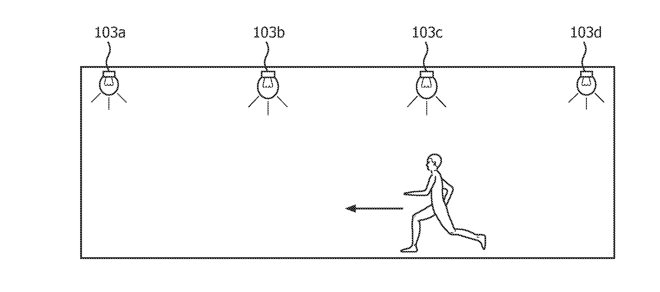
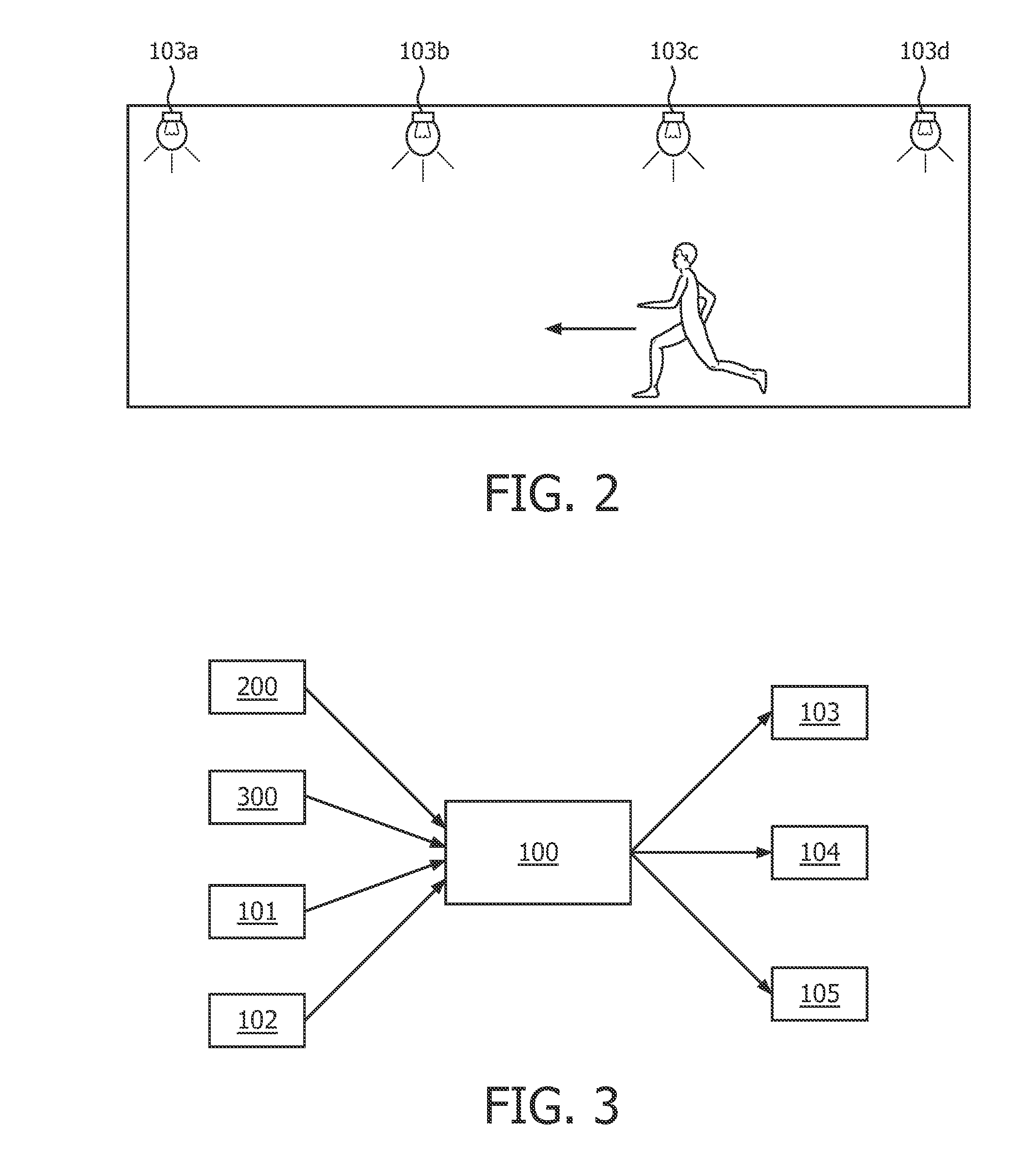
[0023]In another embodiment, the control unit is adapted to control the light unit that is subsequent on a corridor, path or escape route to the light unit closest to a detected person, to emit light at high level, if this light unit has sufficient power available. Thereby, a fleeing person is guided along the escape route in direction of the emergency exit by switching already the next light unit to high level, which is the next to be passed on the escape route. The person can thus follow the light units of high intensity and easily find his direction. If preferred, not only the next light unit but also one or more subsequent light units may be started to emit light at high level, showing the preferred escape route. Moreover, the lighting system may be linked to a Building Management System. This allows to adapt a preferred escape route based on information of the Building Management System. In a more general light guidance system, increasing the light level of the next light unit together with the level of a first light unit, where a person is detected, may make a passerby feel at ease. Also in this case, it may be required to take the power value into account.

Problems solved by technology

In a situation of restricted power supply, however, switching on all light sources of the whole system will soon result in a supply shortfall.
However, if battery level is low and power is cut, a high-intensity illumination will lead to a decreased time period of illumination, possibly contradicting the norm standards.

Method used


Image

  • Light guiding system and a method for controlling the same
  • Light guiding system and a method for controlling the same
  • Light guiding system and a method for controlling the same

Examples


Embodiment Construction

[0030]The light guidance system according to the present invention may be applied as a lighting system for large buildings, underground car parks, public premises or parks. The light guidance system is designed to provide adapted illumination in emergency or power cut situations. The light guidance system may be integrated or communicatingly connected to other systems, e.g. home automation systems, alarm systems or building management systems.

[0031]In an exemplary embodiment, a light guidance system comprises one or more light units and at least one control unit. The light guidance system is connected to an external or public power supply system. In case of a power cut, the light guidance system is powered by an auxiliary power supply system, e.g. batteries, emergency power generators or other self-contained power supply systems, wherein the auxiliary power supply system is charged, when external power is available.

[0032]The light unit located on a ceiling or close to a floor compri...


PUM


Abstract

According to the present invention, a light guidance system for adapted illumination in emergency or power cut situations is provided, wherein the light guidance system is connected to an auxiliary power supply system (101) and comprises at least one light unit (103) adapted to emit light for illuminating surroundings and a control unit adapted to increase a light level of the light unit (103) according to a presence signal indicating the presence of a person, wherein the increasing of the light level is adjusted to enable a mandatory lighting period and a mandatory light level by considering a power value of the auxiliary power supply system (101).

Description

FIELD OF INVENTION[0001]The invention relates to a light guiding system and a method for controlling the same.BACKGROUND OF THE INVENTION[0002]Conventional light guidance systems in an underground car park or public subways employ movement detectors in order to reduce power consumption by switching on light sources only, when a person passes by. In a situation of restricted power supply, however, switching on all light sources of the whole system will soon result in a supply shortfall. Therefore, in many of these systems, the intensity level of emitted light is lower than in a standard illumination for saving energy, although a higher light level would ameliorate the ability of orientation and the feeling of ease and comfort. Normally, these light guidance systems are powered by an external power supply system and the light sources are emitting at a low mandatory intensity level. For power cut situations, the light guidance systems and in particular emergency lighting systems are of...

Claims


Application Information

Patent Timeline
IPC IPC(8): H05B37/02F21Y101/00
CPCG08B7/066H05B37/0245H05B37/0227H02J9/02G08B29/181H05B47/175H05B47/125Y02B20/40H05B47/115G09F27/004H05B47/105
Inventor KNIBBE, ENGEL J.ERTZ, ALEXANDERKLEE, MAREIKEVERHEES, LEO
Owner SIGNIFY HLDG BV
Why Eureka
Eureka Blog
Learn More