
Auxiliary member

a technology of auxiliary members and members, applied in the field of auxiliary members, can solve the problems of increasing costs, poor appearance, and non-uniform installation of solar cell modules, and achieve the effect of correcting the strain on the roof material

Active Publication Date: 2012-07-19
YANEGIJUTSUKENKYUJO CO LTD
View PDF11 Cites 29 Cited by
  • Summary
  • Abstract
  • Description
  • Claims
  • Application Information

AI Technical Summary

Benefits of technology

[0010]In view of the above circumstances, an object of the invention is to provide an auxiliary member which makes it possible to preferably install a solar cell module by inserting the auxiliary member into between a fixing member and a roof material even when an upper surface of the roof material is strained.

Problems solved by technology

Therefore, time and effort is required and the number of parts is large, resulting in a problem of increase in cost.
However, when the solar cell module is fixed directly onto the roof material not through the mount, if flatness of the roof material (for example, roof surface material (roof tile, color best, corrugated plate, and the like), rafter, roof board, and the like) onto which the fixing members are fixed is undesirably swelled or strained, the following problem is caused.
That is, positions (heights) of the plurality of fixing members which support the solar cell module become non-uniform so that the solar cell module cannot be installed in the right direction or the solar cell module cannot be installed.
In addition, when a plurality of solar cell modules are installed on the roof material, there arises a problem that heights at which the solar cell modules are installed become non-uniform so that the entire appearance looks bad.
Conventionally, when a predetermined screw is made to penetrate through the fixing portion of the fixing member and are screwed into the roof material so as to fix the fixing member onto the roof material, there is a risk that rainwater and the like enter the lower side of the roof material down the screwed predetermined screw.
However, in this case, the rubber between the fixing member and the roof material becomes thicker.
Therefore, if the stacked sealing members become thinner due to temperature change by air temperature and the like, change with age, and the like, the fixing of the fixing member onto the roof material becomes unstable, resulting in deterioration of installation strength of the solar cell module.

Method used


Image

  • Auxiliary member
  • Auxiliary member
  • Auxiliary member

Examples


Embodiment Construction

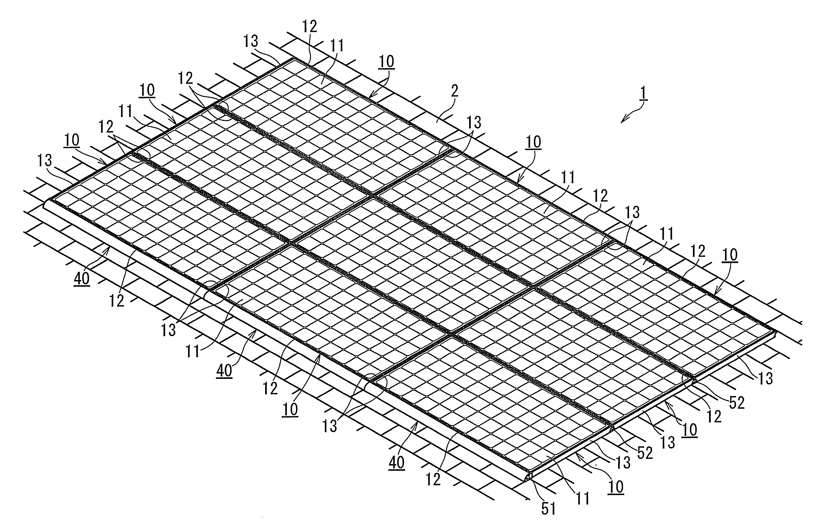
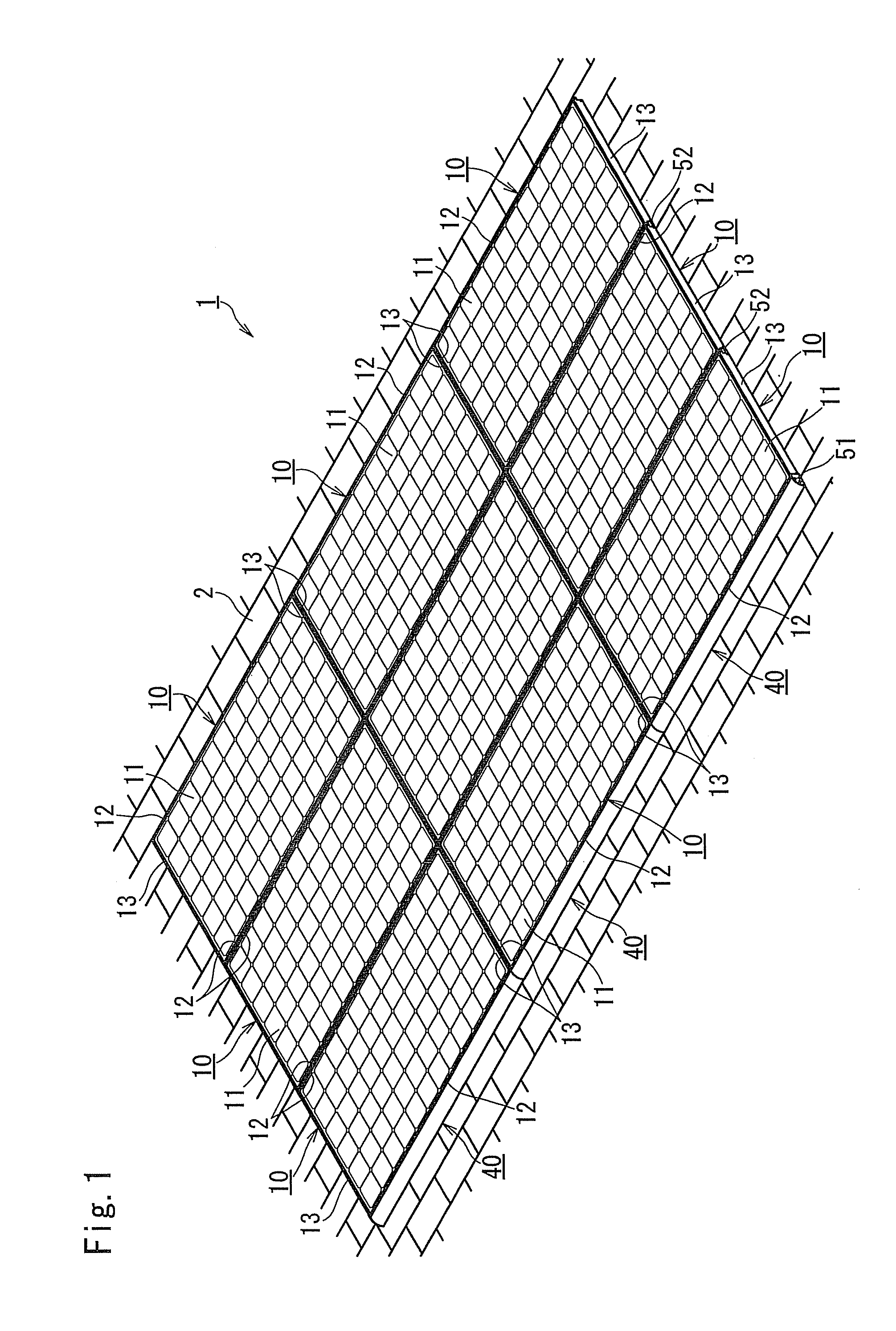
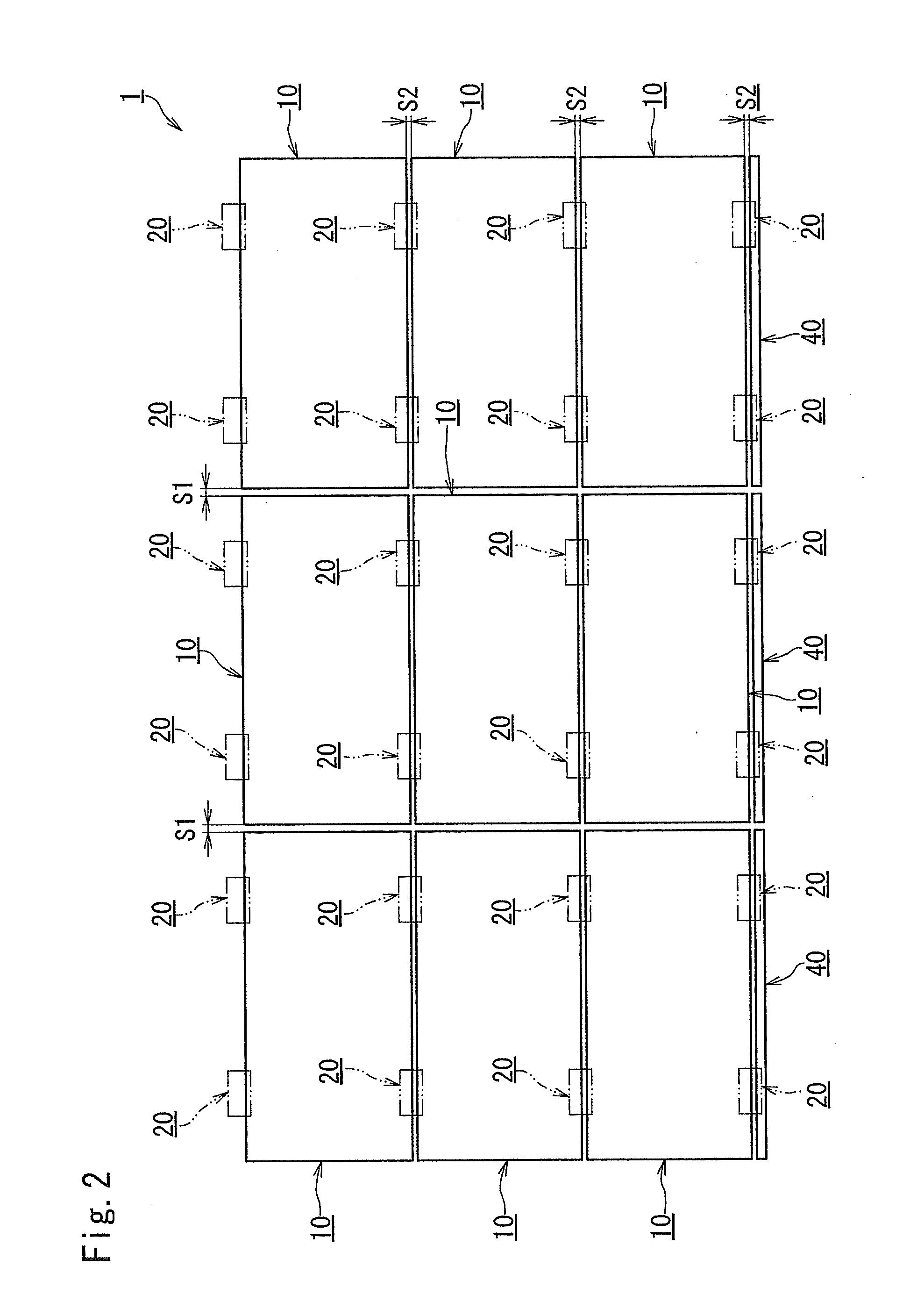
[0040]An auxiliary member which is inserted between a fixing member supporting a solar cell module on a roof material and the roof material according to an embodiment of the invention is described in detail with reference to FIG. 1 through FIG. 5B. FIG. 1 is an entire perspective view illustrating a solar power generation system to which the auxiliary member according to the invention is applied. FIG. 2 is a plan view schematically illustrating the solar power generation system of FIG. 1. FIG. 3 is a side cross-sectional view illustrating primary parts of the invention in the solar power generation system of FIG. 1.

[0041]FIG. 4 is an exploded perspective view illustrating an example of an auxiliary member of FIG. 3 and a fixing member. FIG. 5A is a side view illustrating an example of an auxiliary member in a different form from the example in FIG. 3. FIG. 5B is a perspective view illustrating the auxiliary member of FIG. 5A.

[0042]A solar power generation system 1 to which an auxili...


PUM


Abstract

An auxiliary member which is inserted into between a roof material and a fixing member including a base portion which is placed on the roof material and has a placement portion, a fixing portion, and a concave groove portion, an erected portion which extends to the upper side from the base portion, and a blocking portion which extends from an upper end of the erected portion to both sides so as to be in parallel with the placement portion and blocks the first frame from being moved to the upper side, includes an engagement convex portion which engages with the groove portion of the fixing member, a main body on which the engagement convex portion is formed on an upper surface, and a concave engagement concave portion which is formed on a lower surface of the main body and is engageable with the engagement convex portion.

Description

CROSS REFERENCE TO RELATED APPLICATIONS[0001]This application is national stage of International Patent Application No. PCT / JP2009 / 071527 filed on Dec. 25, 2009.BACKGROUND OF THE INVENTION[0002]1. Field of the Invention[0003]The present invention relates to an auxiliary member which is inserted into between a fixing member supporting a solar cell module on a roof material and the roof material.[0004]2. Description of the Related Art[0005]Conventionally, a solar cell module installed on a roof of a building or the like has been fixed onto a roof material through a mount formed by assembling long frame members in a form of parallel crosses (Japanese Patent Application Laid-open NO. 2006-037545). However, when the solar cell module is installed (supported) through the mount in the form of parallel crosses, the mount in the form of parallel crosses is needed to be built on the roof for installing the solar cell module. Therefore, time and effort is required and the number of parts is la...

Claims


Application Information

Patent Timeline
Patent Type & Authority Applications(United States)
IPC IPC(8): E04D13/18
CPCF24J2/4636F24J2/5207F24J2/5211F24J2/5245F24J2/5249Y02E10/47F24J2002/5215F24J2002/5279F24J2002/529Y02B10/12Y02B10/20F24J2002/4669F24S25/20F24S25/35F24S25/61F24S25/615F24S40/80F24S2025/013F24S2025/019F24S2025/6006F24S2025/801Y02B10/10Y02E10/50H01L31/042H02S20/23
Inventor KOBAYASHI, SHUICHI
Owner YANEGIJUTSUKENKYUJO CO LTD
Learn More