Bending apparatus and bending machine
a technology of bending apparatus and bending machine, which is applied in the direction of electrical apparatus, dynamo-electric machines, manufacturing dynamo-electric machines, etc., can solve the problems of difficult control of material dimension, complex mechanism, and difficulty in combining a plurality of bending apparatuses to bend the material at a plurality of portions simultaneously, so as to ensure the material cannot be pulled, the effect of accurately performing the bending of a flat rectangular wire and excellent quality
- Summary
- Abstract
- Description
- Claims
- Application Information
AI Technical Summary
Benefits of technology
Problems solved by technology
Method used
Image
Examples
first embodiment
[0041]In the following, referring to FIGS. 1 to 6, a first embodiment of the present invention will be described.
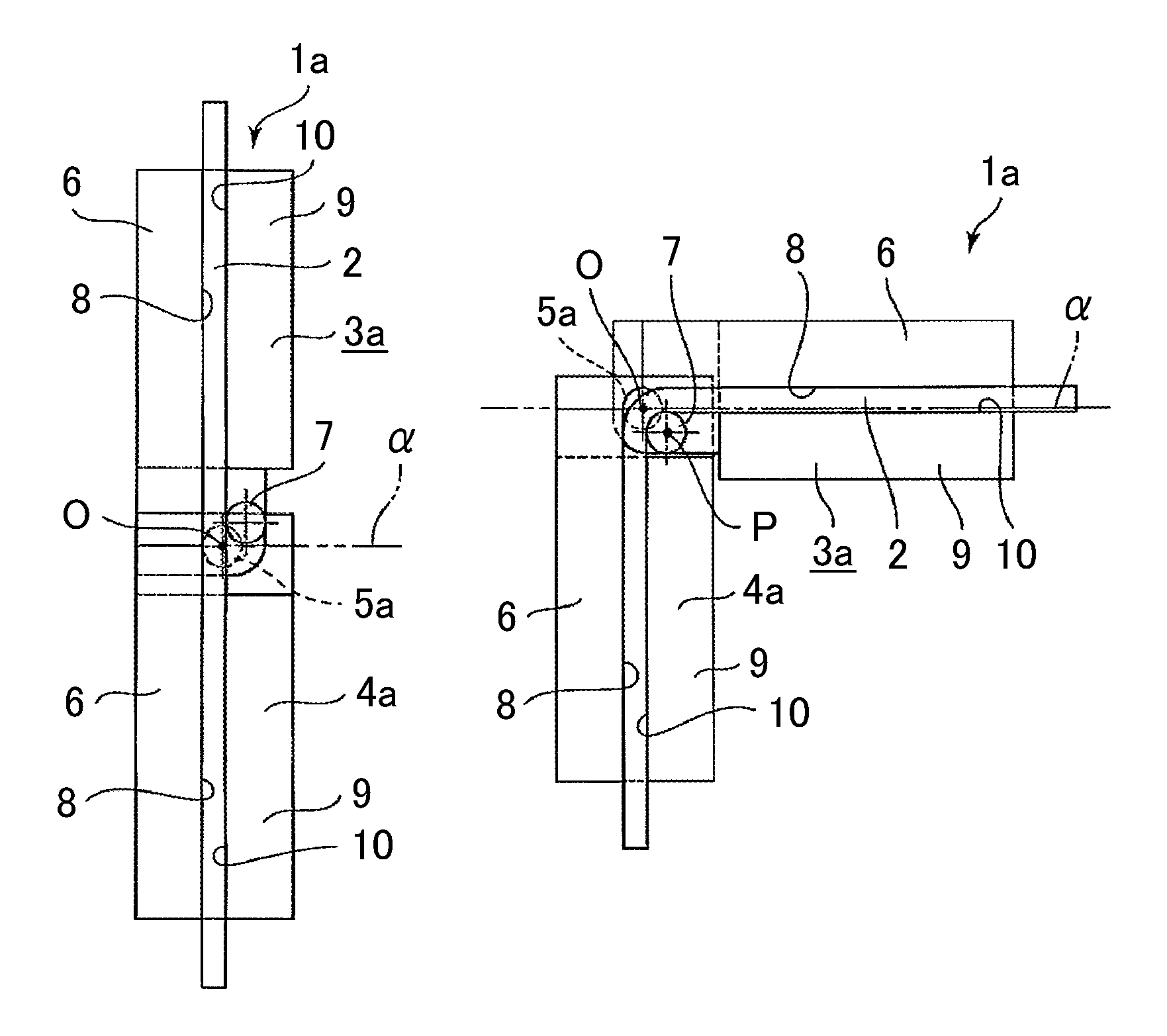
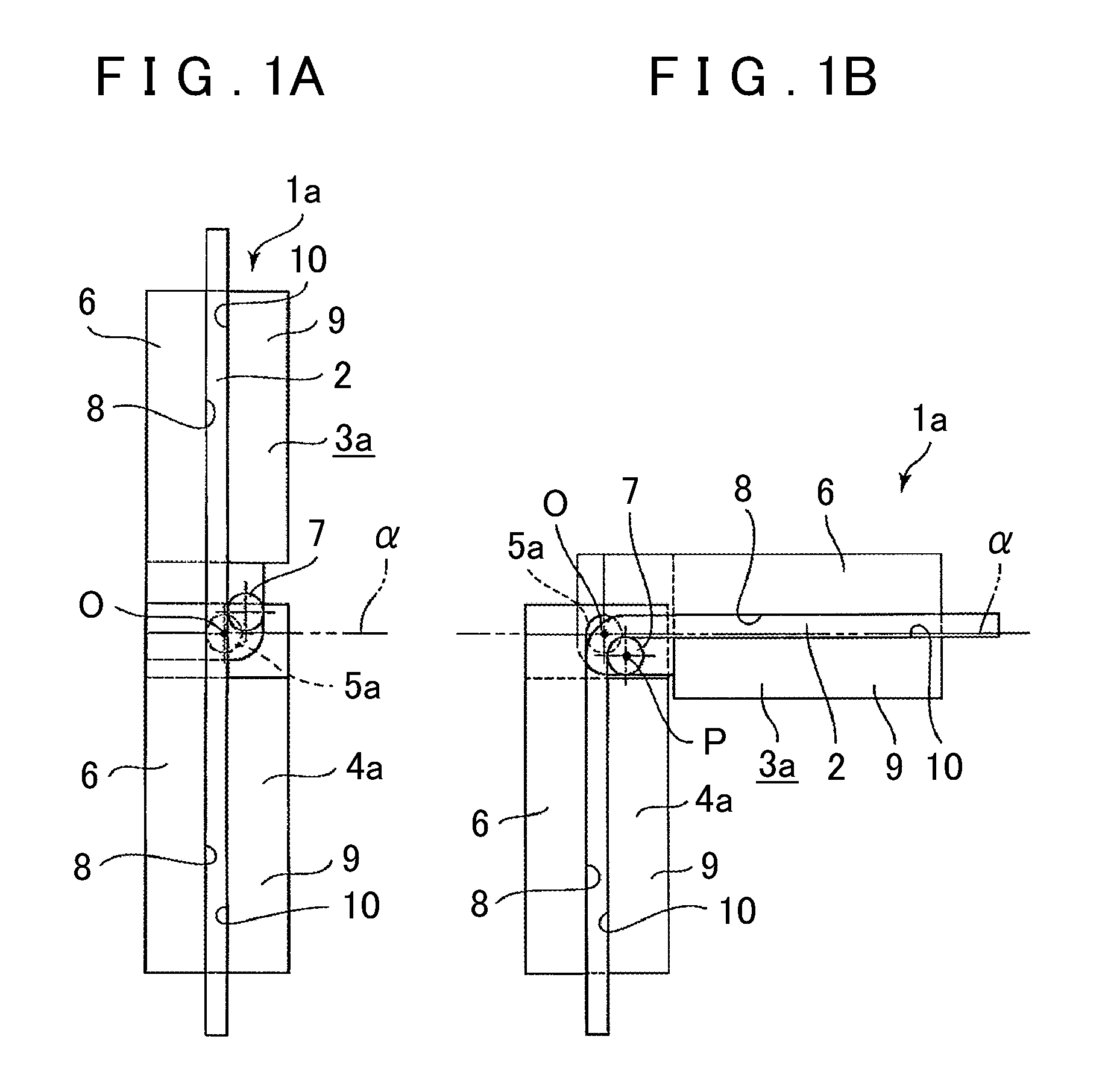
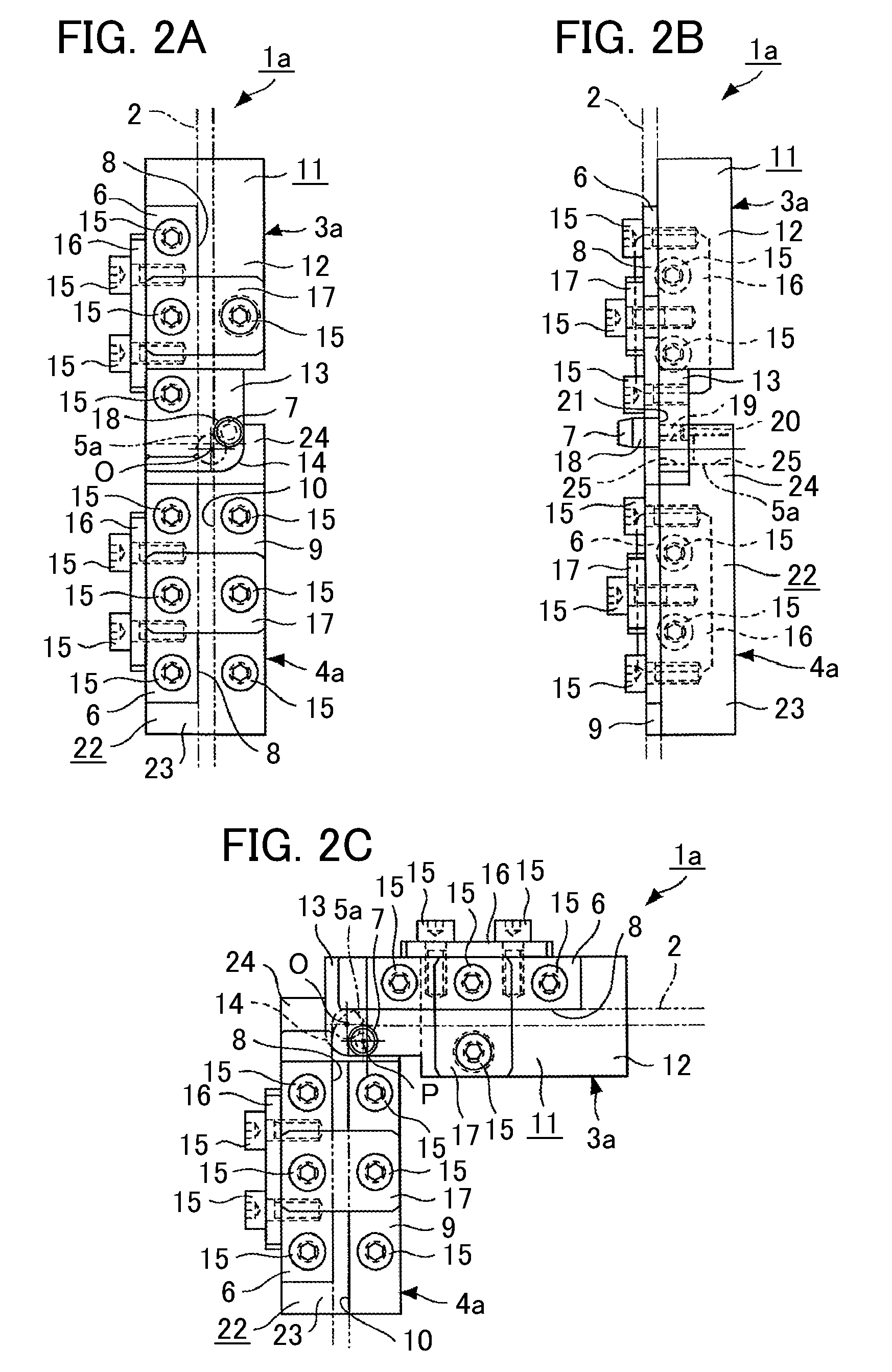
[0042]First, an overview of a bending apparatus 1a of the present embodiment is described referring to a schematic diagram of FIG. 1. The bending apparatus 1a is structured with first and second jigs 3a and 4a that are coupled by a rotary shaft 5a so as to be rotatable relatively to each other. The first jig 3a includes a suppressing section 6, a bending section 7, and a holding section 9. The suppressing section 6 is arranged on the side opposite to the rotating direction of a material 2, e.g., a flat rectangular wire having a rectangular cross section, in a state where the material 2 is arranged at the first jig 3a. In the state where the material 2 is so arranged, a suppressing surface 8 of the suppressing section 6 abuts on the material 2.
[0043]The bending section 7 is formed to have a cylindrical outer peripheral surface, and the center of which is arranged at a posi...
second embodiment
[0070]FIG. 7 shows a bending apparatus 1b according to a second embodiment of the present invention, in which the bending section 7 according to the first embodiment has a modified shape. In the following, description will be given mainly on the difference from the first embodiment.
[0071]As shown in FIG. 7, at a bending section 7a structuring a first jig 3b, a bending cylindrical surface 18a forming a quarter of a circle as seen from the perpendicular direction to the surface of FIG. 7 is formed on the tip surface of a rectangular portion 26 which is elongated along the axial direction of the material 2 and whose cross section perpendicular to the axial direction is rectangular. The bending cylindrical surface 18a is a partially cylindrical surface provided at a contiguous portion between the side surface of the bending section 7a on the material 2 side and the tip surface of the bending section 7a. A center axis (the axis passing through the center of curvature) of the bending cyli...
third embodiment
[0073]FIGS. 8 to 13 show a bending machine 27 according to a third embodiment of the present invention, structured by a combination of a plurality of bending apparatuses such as described above. Each of the bending apparatuses is structured similarly as in the first embodiment. First, an overview of the bending machine 27 according to the present embodiment is described referring to FIG. 8.
[0074]The bending machine 27 is structured by arranging a plurality of bending apparatuses 1a in series, by alternately coupling the first jigs 3a and the second jigs 4a at the rotary centers O, so that the material 2 can be bent at a plurality of portions. To this end, between a pair of end jigs 28a and 28b, three intermediate jigs 29a, 29b and 29c are arranged. Among them, the end jig 28a arranged on the bottom side in FIG. 8A is provided with the second jig 4a at one end (the top side in FIG. 8A). The end jig 28b arranged on the top side in FIG. 8A is provided with the first jig 3a at the other...
PUM
| Property | Measurement | Unit |
|---|---|---|
| radius of curvature | aaaaa | aaaaa |
| displacement | aaaaa | aaaaa |
| center of curvature | aaaaa | aaaaa |
Abstract
Description
Claims
Application Information
 - R&D
- Intellectual Property
- Life Sciences
- Materials
- Tech Scout
- Unparalleled Data Quality
- Higher Quality Content
- 60% Fewer Hallucinations
Browse by: Latest US Patents, China's latest patents, Technical Efficacy Thesaurus, Application Domain, Technology Topic, Popular Technical Reports.
© 2025 PatSnap. All rights reserved.Legal|Privacy policy|Modern Slavery Act Transparency Statement|Sitemap|About US| Contact US: help@patsnap.com


