
Wireless in-core neutron monitor

a neutron monitor and wireless technology, applied in the direction of instruments, nuclear elements, greenhouse gas reduction, etc., can solve the problems of long cable runs, impracticality,

Active Publication Date: 2012-07-12
WESTINGHOUSE ELECTRIC CORP
View PDF15 Cites 51 Cited by
  • Summary
  • Abstract
  • Description
  • Claims
  • Application Information

AI Technical Summary

Benefits of technology

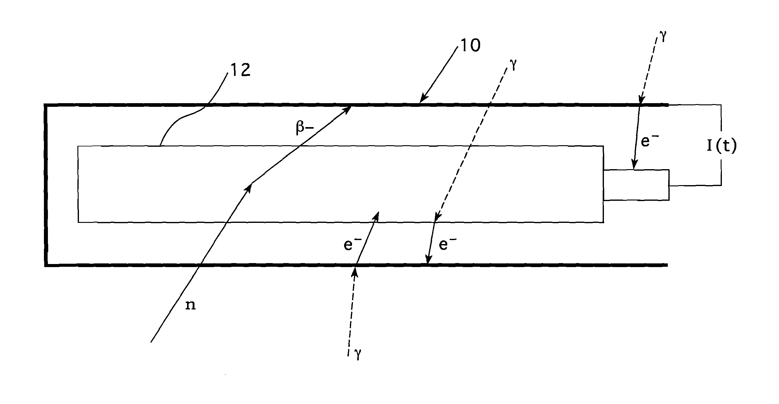
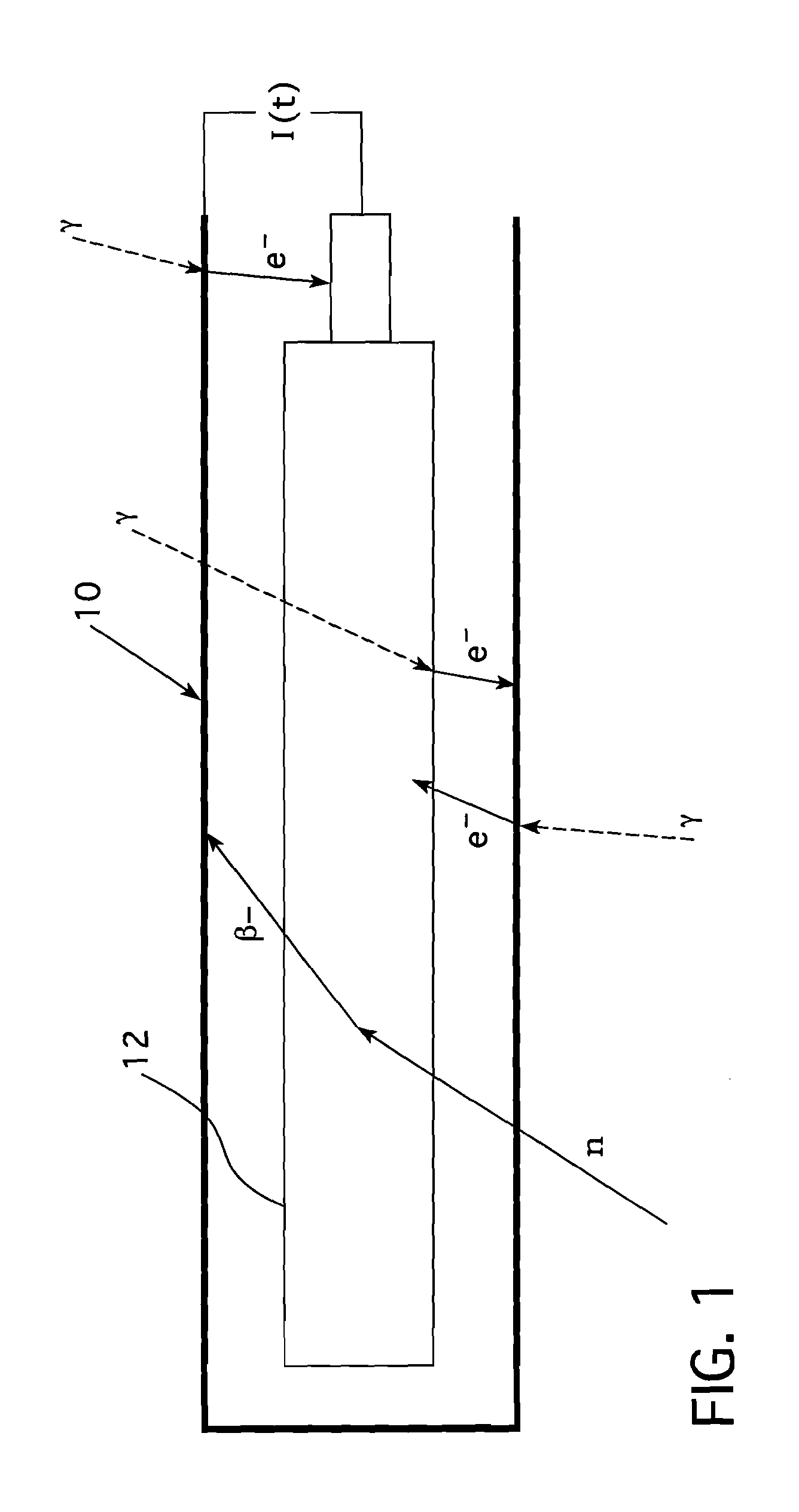
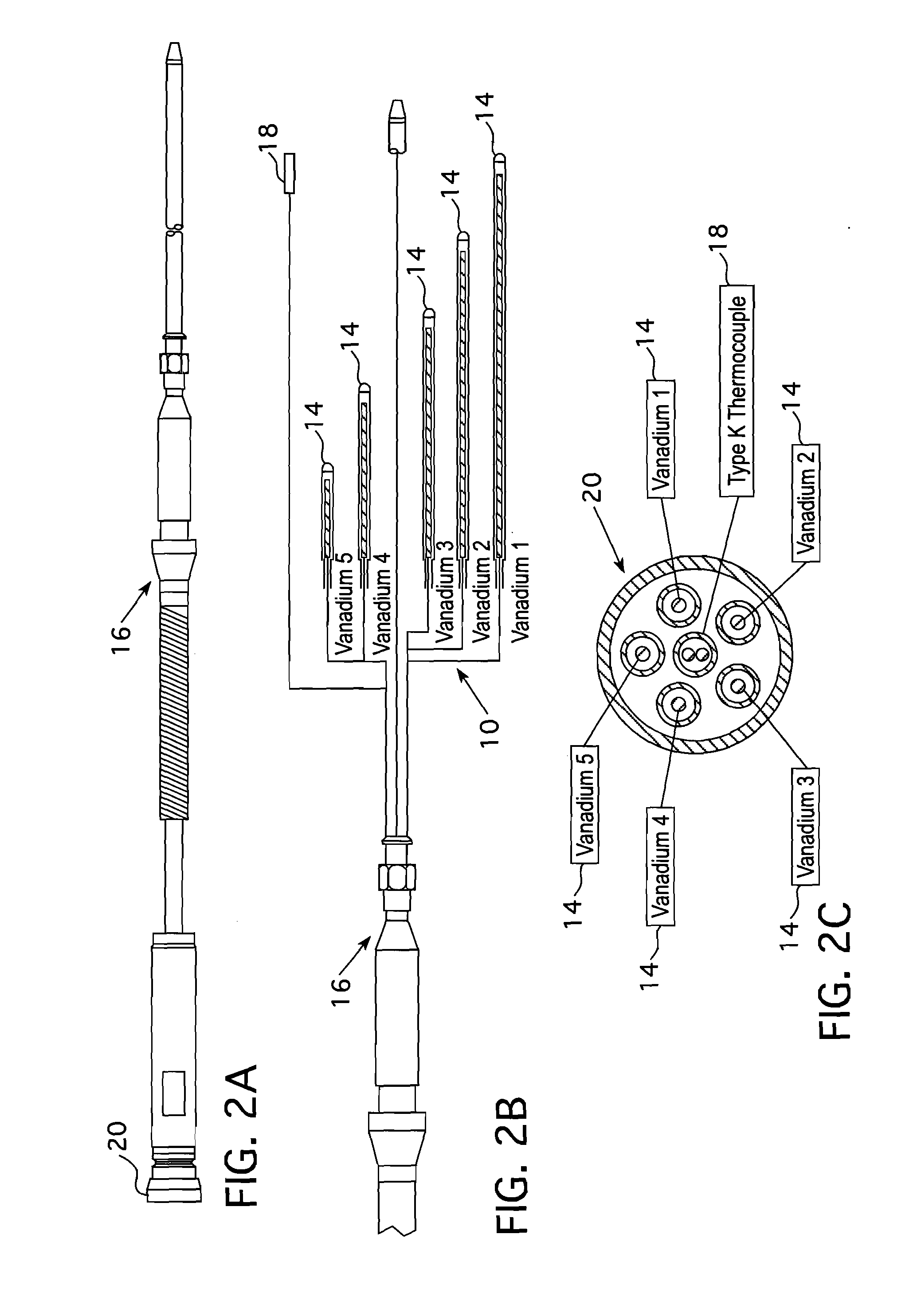
[0012]These and other objectives are achieved by the apparatus of this invention which avoids the necessity of running expensive electrical cables through the reactor head and reactor internals to connect with and energize the in-core instrumentation. In accordance with this invention, a nuclear reactor in-core detector system is provided, including an in-core nuclear instrumentation thimble assembly that is substantially wholly contained within an instrument thimble within a nuclear fuel assembly. The instrument thimble assembly includes a self-powered, fixed, in-core detector for monitoring a reactor core parameter indicative of a state of the reactor core and providing an electric output representative of the monitored parameter. The instrument thimble assembly also includes a wireless transmitter that is connected to receive the electrical output from the self-powered fixed in-core detector and wirelessly transmit that signal to a location outside the reactor. Desirably, the wireless transmitter comprises a number of electronic components at least one of which is a vacuum microelectronic device and, preferably, a vacuum diode placed in a grid circuit of an amplifier which is connected to the electrical output of the self-powered, fixed, in-core detector and responds substantially logarithmically, thus enabling the electronic components to follow the monitored neutron flux from start-up to full power of a nuclear reactor in which the in-core detector system is disposed.

Problems solved by technology

Unfortunately, these long runs of cable have proved necessary because the electronics for signal processing has to be shielded from the highly radioactive environment surrounding the core region.
However, a wireless system requires that electronic components be located at or very near the reactor core where gamma and neutron radiation and high temperatures would render semiconductor electronics inoperable within a very short time.
Vacuum tubes are known to be radiation insensitive, but their size and current demands have made their use impractical until recently.

Method used


Image

  • Wireless in-core neutron monitor
  • Wireless in-core neutron monitor
  • Wireless in-core neutron monitor

Examples


Embodiment Construction

[0029]The primary side of nuclear power generating systems which are cooled with water under pressure comprises a closed circuit which is isolated from and in heat exchange relationship with a secondary side for the production of useful energy. The primary side comprises the reactor vessel enclosing a core internal structure that supports a plurality of fuel assemblies containing fissile material, the primary circuit within heat exchange steam generators, the inner volume a pressurizer, pumps and pipes for circulating pressurized water, the pipes connecting each of the steam generators and pumps to the reactor vessel independently. Each of the parts of the primary side comprising a steam generator, a pump and a system of pipes which are connected to the vessel form a loop of the primary side.

[0030]For the purpose of illustration, FIG. 4 shows a simplified nuclear reactor primary system, including a generally cylindrical reactor pressure vessel 40 having a closure head 42 enclosing a...


PUM


Abstract

An in-core neutron monitor that employs vacuum microelectronic devices to configure an in-core instrument thimble assembly that monitors and wirelessly transmits a number of reactor parameters directly from the core of a nuclear reactor without the use of external cabling. The in-core instrument thimble assembly is substantially wholly contained within an instrument guide tube within a nuclear fuel assembly.

Description

CROSS REFERENCE TO RELATED APPLICATIONS[0001]This application is related to U.S. patent application Ser. No. ______ (Attorney docket NSD2010-006), entitled SELF-POWERED WIRELESS IN-CORE DETECTOR, filed concurrently herewith.BACKGROUND OF THE INVENTION[0002]1. Field of the Invention[0003]The present invention pertains generally to apparatus for monitoring the radiation within the core of a nuclear reactor and, more particularly, to such apparatus that will not obstruct refueling of the reactor.[0004]2. Related Art[0005]In many state-of-the-art nuclear reactor systems in-core sensors are employed for measuring the radioactivity within the core at a number of axial elevations. These sensors are used to measure the radial and axial distribution of the power inside the reactor core. This power distribution measurement information is used to determine whether the reactor is operating within nuclear power distribution limits. The typical in-core sensor used to perform this function is a se...

Claims


Application Information

Patent Timeline
IPC IPC(8): G21C17/108G21C17/00
CPCG21C17/108G21C17/10G21C3/326Y02E30/30G01T3/00G21C17/06
Inventor SEIDEL, JOHN G.FLAMMANG, ROBERT W.CARVAJAL, JORGE V.JAMES, MICHAEL A.ARLIA, NICOLA G.
Owner WESTINGHOUSE ELECTRIC CORP
Learn More