Field emission lamp

Inactive Publication Date: 2012-07-12
TATUNG COMPANY
View PDF5 Cites 0 Cited by
  • Summary
  • Abstract
  • Description
  • Claims
  • Application Information

AI Technical Summary

Benefits of technology

[0008]It is one object of the present invention to provide a field emission lamp capable of increasing the uniformity of the light output therefrom by installing a lens unit.
[0011]Therefore, since the electron is emitted from the cathode portion of the field emission lamp of the present invention, toward the anode portion thereof, until being collided with the phosphor layer. After that, the phosphor layer bombarded by the electrons generates light, the light passes through the lens unit and the inner surface of the outer shell where the anode portion is not formed, and outputs from the field emission lamp. Further, since the lens unit can adjust the characteristics of the light passed through, for example, the lens unit can be a double convex lens or a plano-convex unit which the convex lens structure having the function of focusing the light, or be a double concave lens or a plano-concave lens which the concave lens structure having the function of dispersing the light. Thus, the uniformity of the light emitted from the field emission lamp of the present invention can be increased, and the field emission lamp of the present invention can provide light for different kinds of purpose depending on the different situation, by using different structure of lens unit.
[0012]In addition, the form of the cathode portion of the field emission lamp of the present invention is not limited, the shape thereof can be clavate, or has a curving structure, a spherical structure or a bowl-like structure. Besides, the material of the phosphor layer is not limited, it can be any conventional fluorescent powder, or any conventional phosphor powder suitable for application. Moreover, for different purpose or responding to different requirement, the phosphor layer can be made by mixing one or more kinds of fluorescent powder, or phosphor powder, for emitting UV light, infrared light, white light, or light of other colors. Besides, the form of the lens unit is not limited, any lens unit that can increase the uniformity of the light, or to disperse the light, or to focus the light is suitable for the present invention.

Problems solved by technology

However, in the conventional field emission lamp, the light emitted caused by the electrons bombard the phosphor layer is dot-like light emission, so it would display a non-uniform light emission phenomenon if the density of the dot-like light is not greater enough.
Therefore, while the conventional field emission lamp is under operation, the light emitted from the conventional field emission lamp is always not uniform enough, constraining the usage of the conventional field emission lamp.

Method used


Image

  • Field emission lamp
  • Field emission lamp
  • Field emission lamp

Examples


third embodiment

[0032]With reference to FIG. 3, the field emission lamp of the present invention comprises: an outer shell 31, a cathode portion 32, an anode portion 33, phosphor layer 34, and a lens unit 35. Wherein, the outer shell 31 can be formed by a transparent material, for example, a soda-lime glass. Besides, the material of the outer shell 31 can also be soda glass, boron-glass, flint glass, quartz glass, or alkali-free glass.

[0033]In addition, the outer shell 31 has an inner surface 311, and the light generated by the phosphor layer 34, due to the bombardment of the electrons, outputs from the field emission lamp according to third embodiment of the present invention through the lens unit 35, and then the inner surface 311 of the outer shell 31 where the anode portion 33 is not formed.

[0034]Moreover, in the present embodiment, the outer shell 31 is a bulb-like shell, and the cathode portion 32 is surrounded by the outer shell 31. It should be noticed that, the position of the cathode por...

fourth embodiment

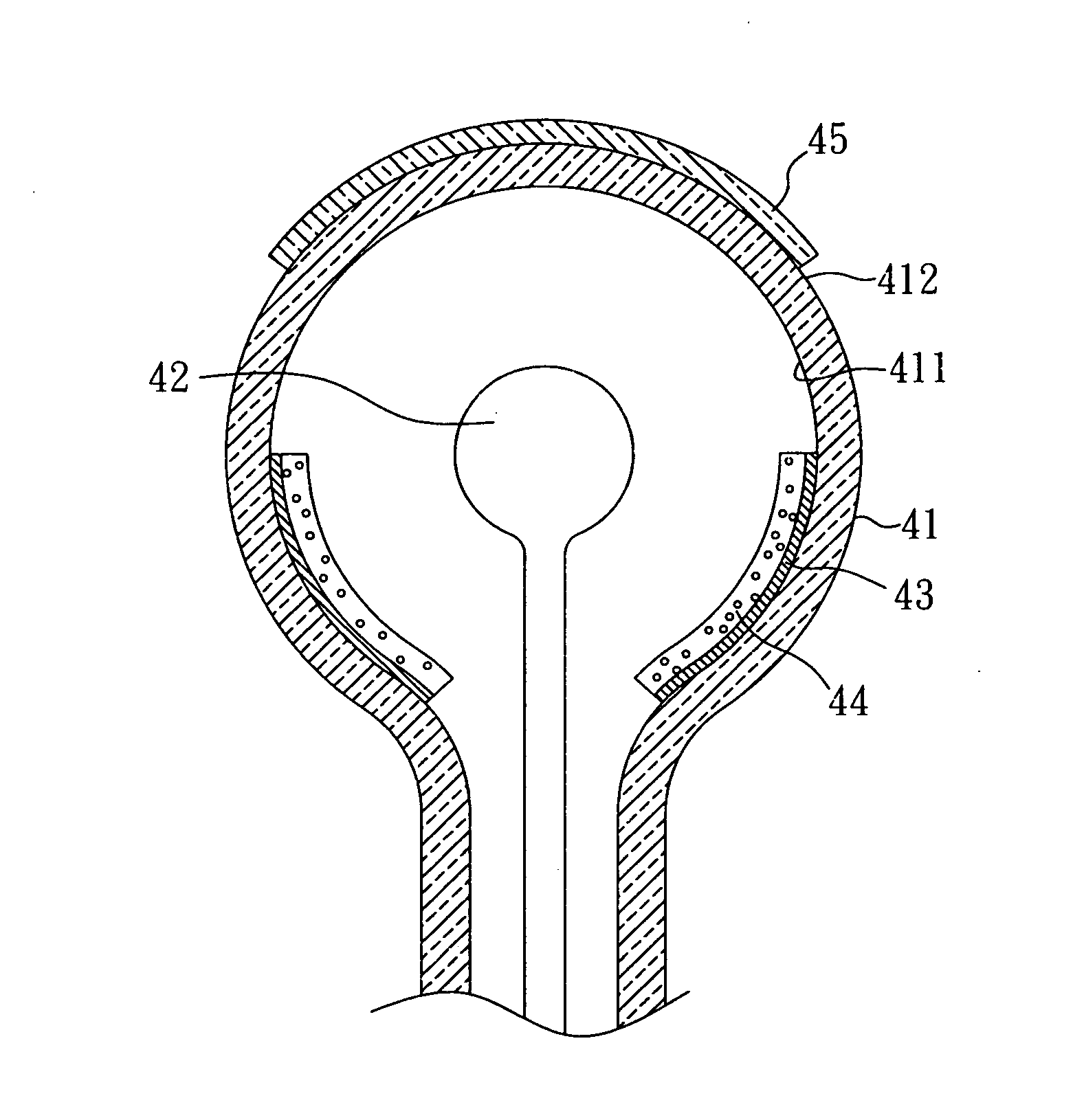
[0041]At final, the lens unit 45 is disposed adjacent to the inner surface 411 of the outer shell 41 where the anode portion 43 is not formed. Actually, as shown in FIG. 4, of the field emission lamp of the present invention, the lens unit 45 is disposed on the outer surface 412 of the outer shell 41(corresponding to the foresaid inner surface 411 where the anode portion 43 is not formed).

[0042]As the structure of the field emission lamp according to fourth embodiment of the present invention is similar to that of the field emission lamp according to second embodiment of the present invention, and the only difference between them are: the shape of the outer shell (tubular vs. bulb-like shape) and the shape of the cathode portion (clavate vs. spherical), the detail description regarding the operation of the field emission lamp according to fourth embodiment of the present invention, such as the mechanism of the generation of light, is omitted hereinafter.

fifth embodiment

[0043]With reference to FIG. 5, wherein FIG. 5 is a perspective view of the field emission lamp of the present invention.

[0044]The field emission lamp according to fifth embodiment of the present invention comprises: an outer shell 51, a cathode portion 52, an anode portion 53, phosphor layer 54, and a lens unit 55. Wherein, the outer shell 51 can be formed by a transparent material, for example, a soda-lime glass. Besides, the outer shell 51 has an inner surface 511, and the light generated by the phosphor layer 54, due to the bombardment of the electrons, outputs from the field emission lamp according to fifth embodiment of the present invention through the inner surface 511 of the outer shell 51 where the anode portion 53 is not formed, and then the lens unit 55. In addition, in the present embodiment, the cathode portion 52 is a mesh-type cathode portion for increasing the number of electron emitting points thereof, to further increase the uniformity and the intensity of the li...


PUM


Abstract

A field emission lamp, capable of increasing the number of electron emitting points thereof, and of increasing the uniformity and the intensity of the light output therefrom by installing a lens unit is disclosed. The field emission lamp comprises: an outer shell having an inner surface, an anode portion formed on a portion of the inner surface of the outer shell, a cathode portion surrounded by the outer shell, a phosphor layer formed on a portion of the anode portion, and a lens unit disposed adjacent to the inner surface of the outer shell where the anode portion is not formed. Wherein, the phosphor layer generates light due to the bombardment of the electrons, the light passes through the lens unit and the inner surface of the outer shell where the anode portion is not formed, and outputs from the field emission lamp.

Description

CROSS REFERENCE TO RELATED APPLICATION[0001]This application claims the benefits of the Taiwan Patent Application Ser. No. 100100506, filed on Jan. 6, 2011, the subject matter of which is incorporated herein by reference.BACKGROUND OF THE INVENTION[0002]1. Field of the Invention[0003]The present invention relates to a field emission lamp and, more particularly, to a field emission lamp capable of increasing the uniformity of the light output therefrom by installing a lens unit, and of forming an anode portion on a portion of the inner surface of the outer shell thereof.[0004]2. Description of Related Art[0005]A conventional field emission lamp comprises: a transparent outer shell, an anode portion, a cathode portion, and a phosphor layer. The anode portion and the phosphor layer are formed on an inner surface of the transparent outer shell in sequence. The cathode portion is installed on a central position inside the transparent outer shell. Besides, the operation mechanism of the c...

Claims


Application Information

Patent Timeline
IPC IPC(8): H01J63/04
CPCH01J61/025H01J63/06H01J63/02
Inventor YANG, TZUNG-HAN
Owner TATUNG COMPANY
Why Eureka
Try Eureka