
Apparatus for preoperative planning of artificial knee joint replacement operation and jig for supporting operation

a knee joint replacement and preoperative planning technology, applied in the direction of prosthesis, instruments, image enhancement, etc., can solve the problems of insufficient measurement accuracy of size and position, the installation position, and insufficient knowledge of the cutting angle, etc., to achieve the effect of accurately determining the position and angle of the distal bone cutting surfa

Inactive Publication Date: 2012-07-05
LEXI CO LTD
View PDF1 Cites 14 Cited by
  • Summary
  • Abstract
  • Description
  • Claims
  • Application Information

AI Technical Summary

Benefits of technology

"The present invention provides an apparatus and jig for preoperative planning and supporting an artificial knee joint replacement operation. The apparatus includes means for inputting an image and reconstructing a three-dimensional image of the knee joint, means for determining the artificial joint to be replaced, and means for determining various parameters used in the replacement using an alignment rod in the marrow. The jig includes a contact portion that contacts the reference point of the knee joint, a mounting portion that mounts the alignment rod, and an arm portion that connects the contact portion with the mounting portion and can adjust the attaching position and angle of the mounting portion. The technical effects of the invention include accurately determining the position and angle of the distal bone cutting surface and properly reflecting differences in patients, resulting in an exact surgery by recreating the content determined from the reference points of the femur knee joint using a jig for exclusive use during the operation."

Problems solved by technology

In the manual measurement using the template and the ruler on the basis of the two-dimensional simple X-ray image, the measurement accuracy of the size and position is insufficient.
In addition, it is difficult to figure out the installation position and the extent of bone cutting three-dimensionally and quantitatively.
Therefore, considerable experience and accumulation of technique are needed.
Consequently, it has been difficult for all the orthopedists to immediately perform the exact and highly accurate operation planning and operation.
In the method using the two-dimensional template, it has been difficult to perform such processing.
However, the flexion-extension angle cannot be adjusted and is completely dependent on the insertion angle of the rod in the marrow.
Thus, it is difficult to reliably form a distal bone cutting surface at a prearranged angle.
Thus, when the distal bone cutting surface in itself is inaccurate, the rotation angle is inevitably inaccurate.

Method used


Image

  • Apparatus for preoperative planning of artificial knee joint replacement operation and jig for supporting operation
  • Apparatus for preoperative planning of artificial knee joint replacement operation and jig for supporting operation
  • Apparatus for preoperative planning of artificial knee joint replacement operation and jig for supporting operation

Examples


Embodiment Construction

[0039]Hereinafter, one embodiment of the present invention will be described with reference to drawings.

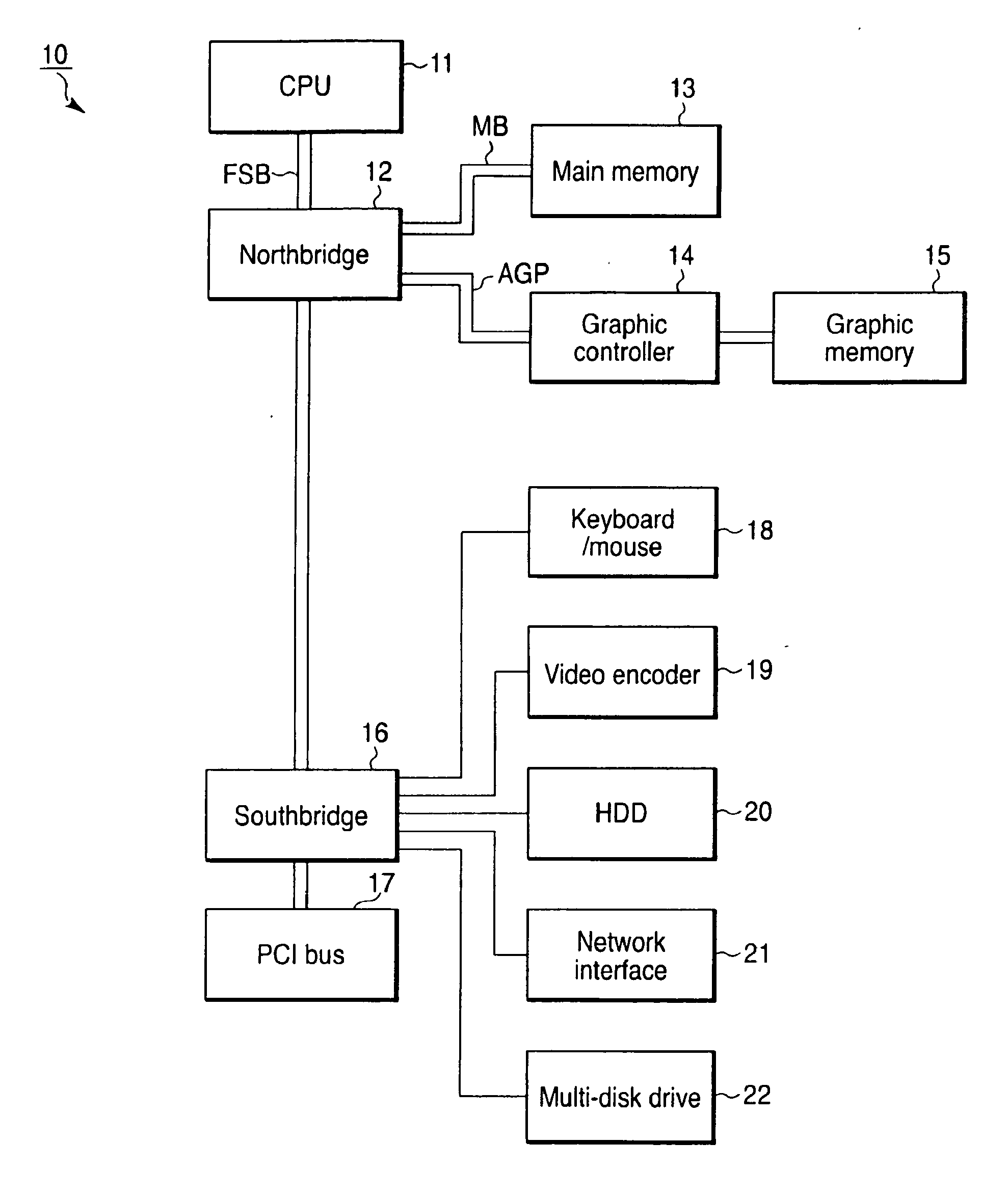
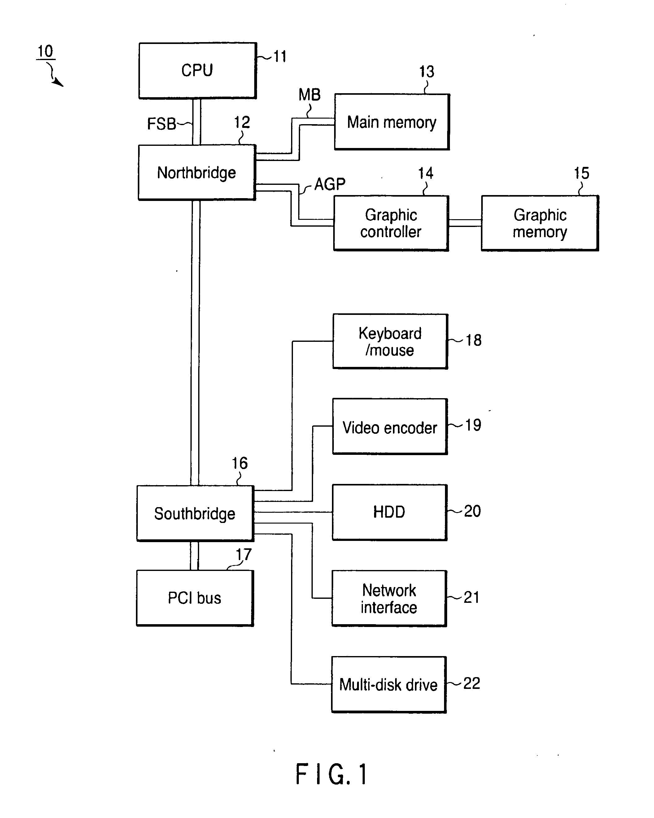
[0040]FIG. 1 is a hardware configuration of a personal computer (hereinafter referred to as a “PC”) 10 in which a program for preoperative planning of an artificial knee joint replacement operation is installed. A CPU 11 which manages various processing controls is connected to a northbridge 12 via a front side bus (FSB).

[0041]The northbridge 12 is further connected to a main memory 13 via a memory bus (MB) and is connected to a graphic controller 14 and a graphic memory 15 via an AGP graphics interface. In addition, it is also connected to a southbridge 16 and mainly performs input-output control thereof.

[0042]The southbridge 16 is connected to a PCI bus 17, a keyboard / mouse 18, a video encoder 19, a hard disk drive (HDD) 20, a network interface 21, and a multi-disk drive 22 and mainly performs input-output control of these peripheral circuits and the northbridge 12.

[0043]An oper...


PUM


Abstract

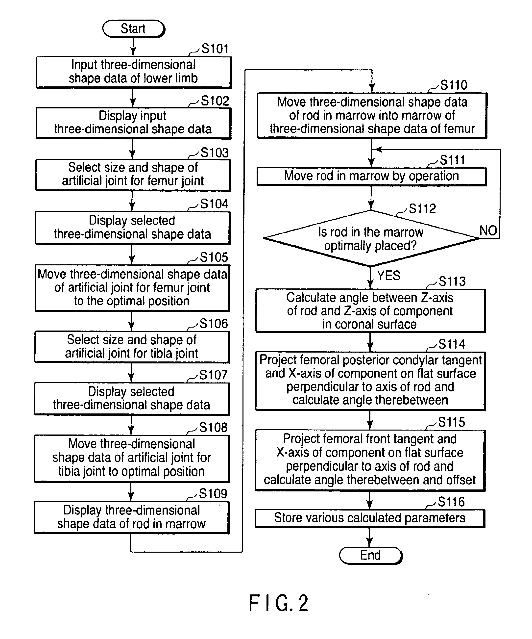
Steps S101 and S102 of displaying images which input two-dimensional tomographic images of the lower limb including the knee joint and displays three-dimensional images of the femur and the tibia including the knee joint from the image input, steps S103 to S105 and S106 to S108 of determining artificial joint which determine the artificial joint to be replaced from the three-dimensional images of each knee joint of the femur and tibia, and steps S113 and S114 of parameter determination which determine various parameters used in an artificial knee joint replacement operation using an alignment rod in the marrow to be inserted into the femur based on the artificial joint and reference points of the knee joint determined in steps S103 to S105 of determining femur side artificial joint are performed by a computer.

Description

CROSS REFERENCE TO RELATED APPLICATIONS[0001]This is a Continuation Application of PCT Application No. PCT / JP2008 / 065900, filed Sep. 3, 2008, which was published under PCT Article 21(2) in Japanese.[0002]This application is based upon and claims the benefit of priority from prior Japanese Patent Application No. 2007-256046, filed Sep. 28, 2007, the entire contents of which are incorporated herein by reference.BACKGROUND OF THE INVENTION[0003]1. Field of the Invention[0004]The present invention relates to an apparatus for preoperative planning of an artificial knee joint replacement operation and a jig for supporting the operation in order to plan an artificial knee joint replacement operation for the knee of the human body using a tomographic image for medical use and perform the operation.[0005]2. Description of the Related Art[0006]In recent years, tomographic image diagnostic apparatuses such as X-ray CT scanners and MRI apparatuses have spread. The use of these apparatuses allow...

Claims


Application Information

Patent Timeline
Patent Type & Authority Applications(United States)
IPC IPC(8): A61B17/56
CPCA61B17/155A61B17/1764A61B17/72A61B19/50A61B19/56A61B2019/501G06T2211/40A61B2019/508G06T7/0022G06T11/006G06T2207/10081G06T2207/10088G06T2207/30008A61B2019/505A61B2034/101A61B34/25A61B34/10A61B2034/105A61B2034/108G06T7/97
Inventor SATO, TAKASHI
Owner LEXI CO LTD
Learn More