
Sputtering apparatus and manufacturing method of electronic device

Inactive Publication Date: 2012-06-28
CANON ANELVA CORP
View PDF2 Cites 36 Cited by
  • Summary
  • Abstract
  • Description
  • Claims
  • Application Information

AI Technical Summary

Benefits of technology

[0010]Thus, the present invention is made in consideration of the conventional problem and provides a sputtering apparatus that can efficiently laminate thin films in a short time without lowering throughputs, and a manufacturing method of an electronic device using the sputtering apparatus.
[0013]According to the present invention, it is possible to provide a sputtering apparatus that can efficiently laminate thin films in a short time without lowering throughputs, and a manufacturing method of an electronic device using the sputtering apparatus.

Problems solved by technology

Therefore, film formation is continued even while the target is exposed to the substrate and the shielding shutter is opened / closed and thus, the film formation rate during the period is unstable.
For this reason, although it is needed to shorten the film formation time (for example, three to six seconds per layer), the total number of revolutions of the substrate is small in such short time, resulting in that the shutter opening / closing time occupied in the film formation time cannot be ignored.
Since the film formed before opening of the shutter and the film formed after complete opening of the shutter are mixed, in-plane distribution becomes disadvantageously nonuniform.
In addition, although such problem can be solved by rotating the substrate holder at higher speed, the speed of a motor for rotating the substrate holder has already reached a physical limit.

Method used


Image

  • Sputtering apparatus and manufacturing method of electronic device
  • Sputtering apparatus and manufacturing method of electronic device
  • Sputtering apparatus and manufacturing method of electronic device

Examples


Embodiment Construction

[0028]An embodiment for implementing the present invention will be described below with reference to figures.

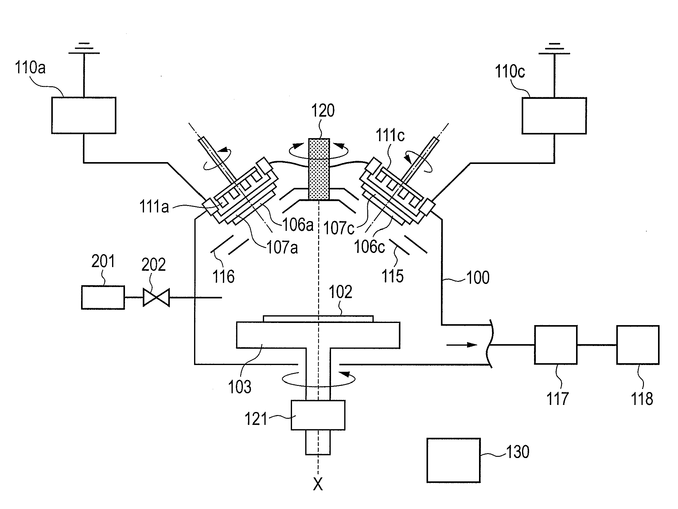
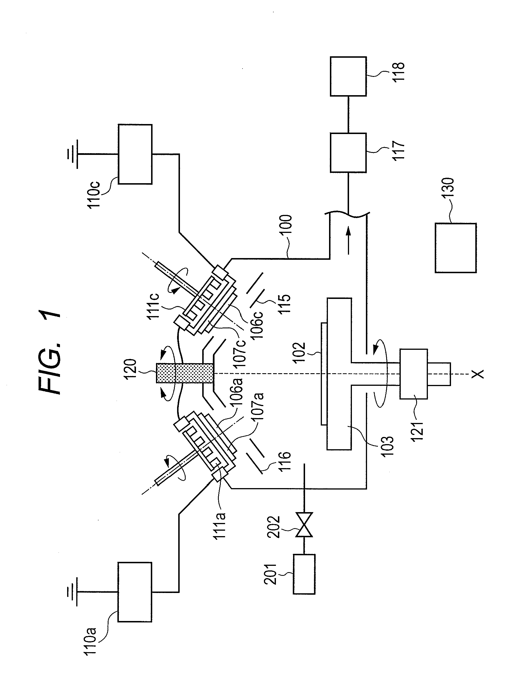
[0029]Referring to FIG. 1, a sputtering apparatus according to an embodiment of the present invention will be described.

[0030]The sputtering apparatus can manufacture an electronic device such as MRAM. The sputtering apparatus includes a treatment chamber 100, a substrate holder 103 for holding a substrate, the substrate holder 103 being provided in the treatment chamber so as to be rotatable about a rotational axis perpendicular to a film formation surface of the substrate, a rotation driving part 121 as a rotation driving means for rotating the substrate holder 103, and a target holder group having target holders 107a to 107d provided so that a perpendicular line which is perpendicular to a plane including the film formation surface of the substrate and which passes the center of the substrate, does not match a perpendicular line passing the center of a target. Each of the ...


PUM

PropertyMeasurementUnit
Poweraaaaaaaaaa

Abstract

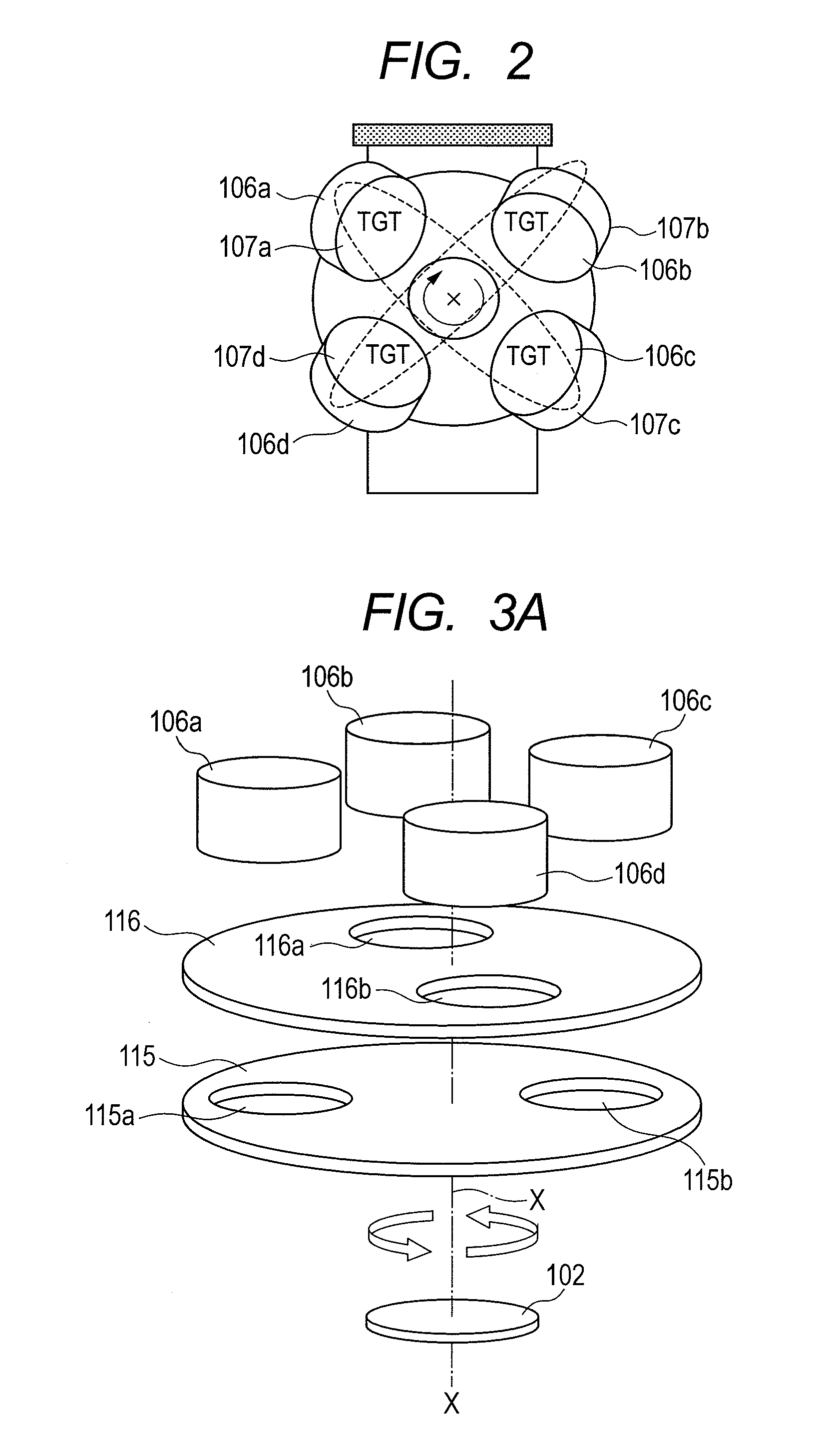
The present invention provides a sputtering apparatus that can efficiently laminate thin films in a short time without lowering throughputs, and a manufacturing method of an electronic device. The sputtering apparatus according to an embodiment of the present invention includes a rotatable substrate holder, four target holders obliquely arranged with respect to the substrate holder, and a first shutter and a second shutter that each are provided between the target holders and the substrate holder and have two holes arranged two-fold symmetrical with respect to a rotational axis X. Two of the four target holders are first group target holders arranged two-fold symmetrical with respect to the rotational axis X, and the other two target holders are second group target holders arranged between the first group target holders and two-fold symmetrical with respect to the rotational axis X.

Description

CROSS-REFERENCES TO RELATED APPLICATIONS[0001]This application claims the benefit of Japanese Patent Application Nos. 2010-293527, filed Dec. 28, 2010 and 2011-243539, filed Nov. 7, 2011. The contents of the aforementioned applications are incorporated herein by reference in their entirety.BACKGROUND OF THE INVENTION[0002]1. Field of the Invention[0003]The present invention relates to a sputtering apparatus and a manufacturing method of an electronic device.[0004]2. Description of the Related Art[0005]To form a uniform ultrathin film by sputtering, a so-called oblique sputtering film formation method of obliquely injecting sputtering particles to a rotating substrate to form a film has been conventionally employed. Japanese Patent Application Laid-Open No. 2009-68075 discloses a sputtering apparatus including a plurality of targets and a shutter plate having a plurality of openings with respect to a substrate.[0006]In recent years, to manufacture a magnetic random access memory (MRA...

Claims


Application Information

Patent Timeline
IPC IPC(8): C23C14/34
CPCC23C14/185C23C14/352H01J37/3447H01J37/3417H01J37/3435C23C14/505
Inventor OTANI, YUICHIYAMAGUCHI, NOBUO
Owner CANON ANELVA CORP
Learn More