
Inverter stack

Active Publication Date: 2012-06-28
LG ELECTRONICS INC
View PDF10 Cites 23 Cited by
  • Summary
  • Abstract
  • Description
  • Claims
  • Application Information

AI Technical Summary

Benefits of technology

[0011]In order to solve the foregoing problem, one aspect of the detailed description is to provide an inverter stack capable of suppressing the damage of components due to high temperature.
[0012]Furthermore, another aspect of the present disclosure is to provide an inverter stack capable of shortening the path of heat dissipation to suppress temperature increase.
[0013]In addition, still another aspect of the present disclosure is to provide an inverter stack capable of reducing the capacity of a cooling apparatus to decrease the overall size of a device as well as reduce the production cost.

Problems solved by technology

However, in the inverter stack in the related art, a circuit unit is provided without taking sufficient consideration on the heating relations of components, thereby accelerating the enforced deterioration of peripheral components due to heat generated by high heat dissipation components.
In particular, for other components disposed adjacent to high-temperature heat dissipation components, it may cause life reduction and / or performance degradation due to high heat directly transferred from the high heat dissipation components.
Furthermore, when high heat dissipation components are disposed far apart from an outlet port without taking sufficient consideration on the heating relations of components, the dissipation of heat generated from the high heat dissipation components is delayed, thereby increasing an internal temperature of the enclosure.
Taking such points into consideration, when the capacity of a cooling apparatus is increased, it may increase the consumption power of the cooling apparatus, thereby increasing the size of an overall device as well as raising the production cost.

Method used


Image

  • Inverter stack
  • Inverter stack
  • Inverter stack

Examples


Embodiment Construction

[0042]Hereinafter, the present invention will be described in detail with reference to the accompanying drawings.

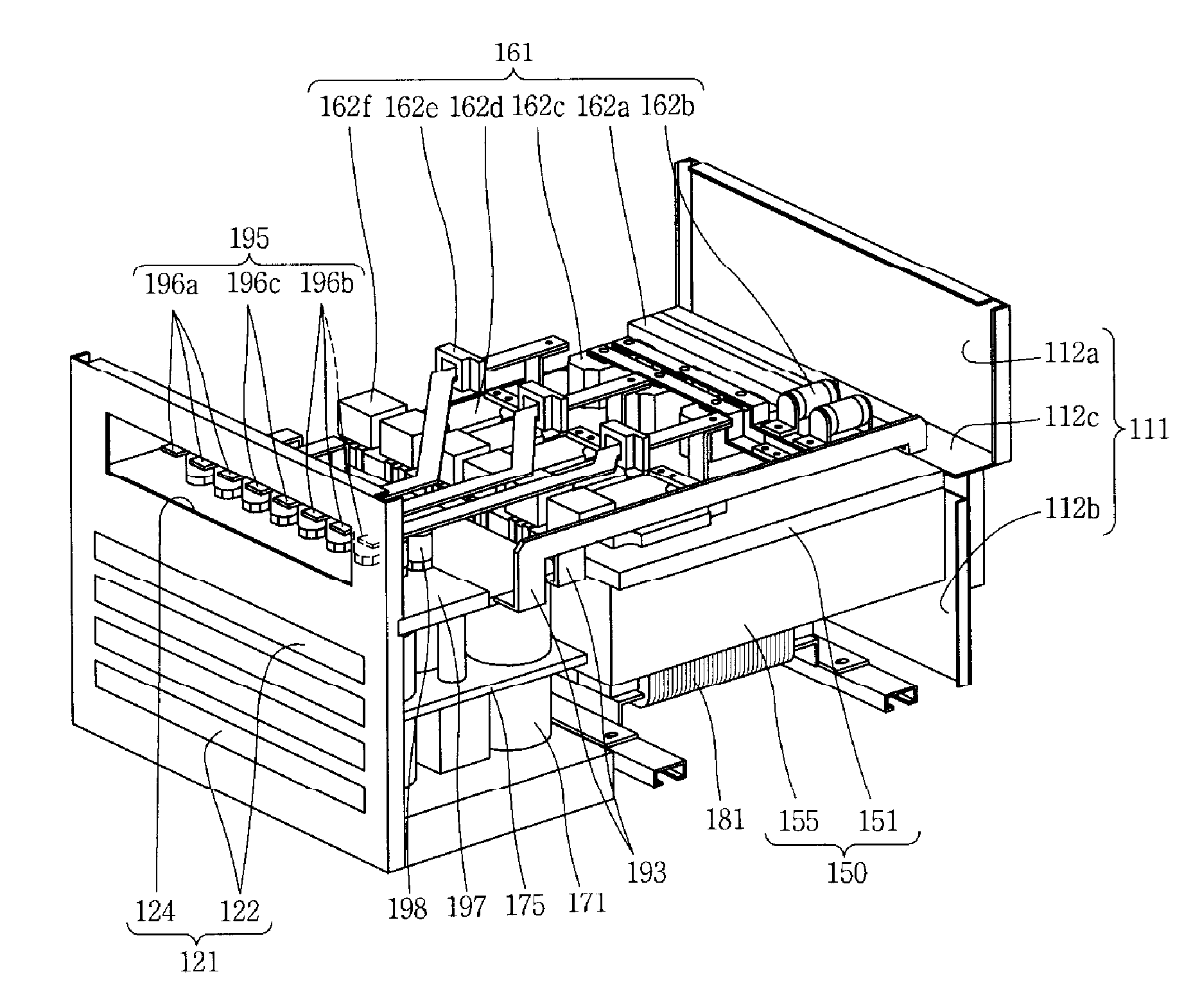
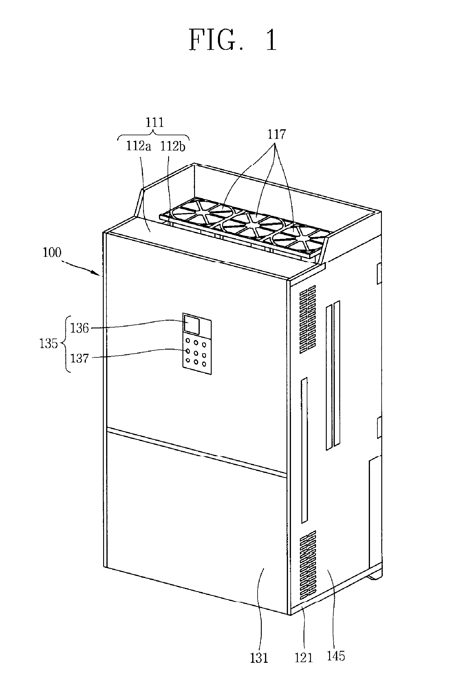
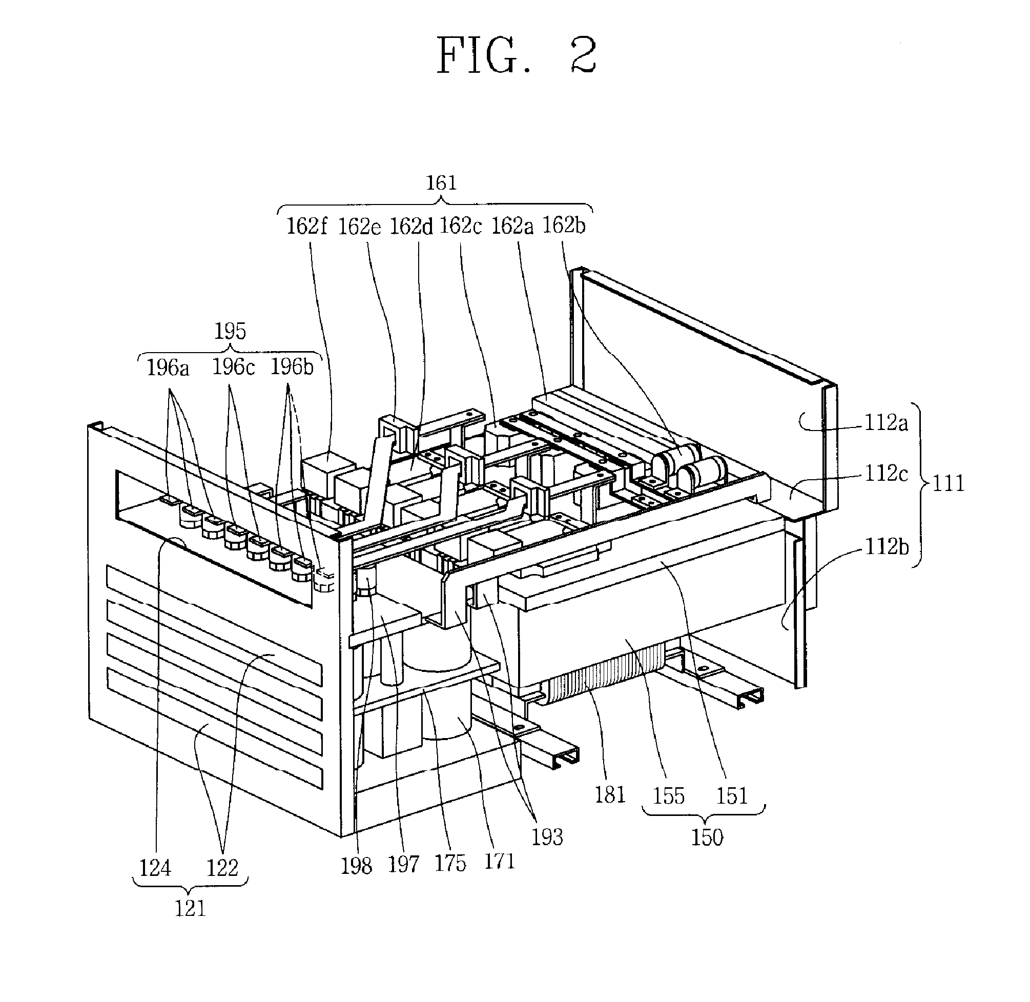
[0043]As illustrated in FIG. 1, an inverter stack according to an embodiment of the present disclosure may include an enclosure 100 on which an inlet port 122 is formed at a lower end thereof and an outlet port 115 is formed at an upper end thereof; a heat sink 150 having a switching element 162d, disposed at an internal upper region of the enclosure 100; and a plurality of DC-link capacitors 171 disposed at a lower side of the heat sink 150.

[0044]The enclosure 100 may be configured with a rectangular parallelepiped formed with an accommodation space therein.

[0045]The enclosure 100 may be formed to have a long vertical length.

[0046]The enclosure 100 may include a bottom plate 121 disposed at a bottom portion thereof, an upper plate 111 disposed at an upper side of the bottom plate 121 to be separated therefrom by a predetermined distance, a front surface plate 131, a rear...


PUM


Abstract

An inverter stack includes an enclosure on which an inlet port is formed at a lower end thereof and an outlet port is formed at an upper end thereof, the enclosure defining an internal space, a heat sink having a switching element, disposed within an upper region of the internal space, and a plurality of DC-link capacitors disposed within the internal space and below the heat sink. Through this, heat generated in high heat dissipation components is immediately moved upward by convection, thereby suppressing the damage of components due to high temperature.

Description

CROSS-REFERENCE TO RELATED APPLICATIONS[0001]The present disclosure relates to subject matter contained in priority Korean Application No. 10-2010-0134887, filed on Dec. 24, 2010, which is herein expressly incorporated by reference in its entirety.BACKGROUND OF THE INVENTION[0002]1. Field of the Invention[0003]The present disclosure relates to an inverter stack, and more particularly, to an inverter stack for suppressing an adverse effect on due to high temperature by improving its cooling performance.[0004]2. Description of the Related Art[0005]As is generally known, an inverter or inverter stack is an apparatus for converting direct-current power to high-frequency alternate-current power.[0006]Such an inverter stack is widely used in driving a high-frequency induction heater or three-phase AC motor for heating metal or the like using high-frequency power.[0007]The inverter stack may include an enclosure forming an accommodation space therein, and a circuit unit (inverter) having a...

Claims


Application Information

Patent Timeline
IPC IPC(8): H05K7/20
CPCH05K7/20909
Inventor KIM, JUNGBUMYIM, NAMSIKSONG, HYEOKJINLEE, BEOMSEOKRYU, SEUNGHEELEE, DONGCHEOL
Owner LG ELECTRONICS INC
Learn More