
Hydraulic flange connection

a technology of flange connection and flange, which is applied in the direction of flanged joints, pipe joints, mechanical equipment, etc., can solve the problems of cyclic fatigue, failure, and shortened service life of connectors, and achieves a wide range of axial forces, reduce stress levels, and facilitate manufacturing

Inactive Publication Date: 2012-06-28
EATON CORP
View PDF10 Cites 6 Cited by
  • Summary
  • Abstract
  • Description
  • Claims
  • Application Information

AI Technical Summary

Benefits of technology

[0004]In order to improve the performance and reduce the material thickness and allow for alternative materials to be utilized in the manufacture and use of a flange connector, an improved flange connector is disclosed herein. This improved mechanical flange connector can be used to provide a fluid flow path and connect pressurized hydraulic system components, especially those experiencing high operating pressures.
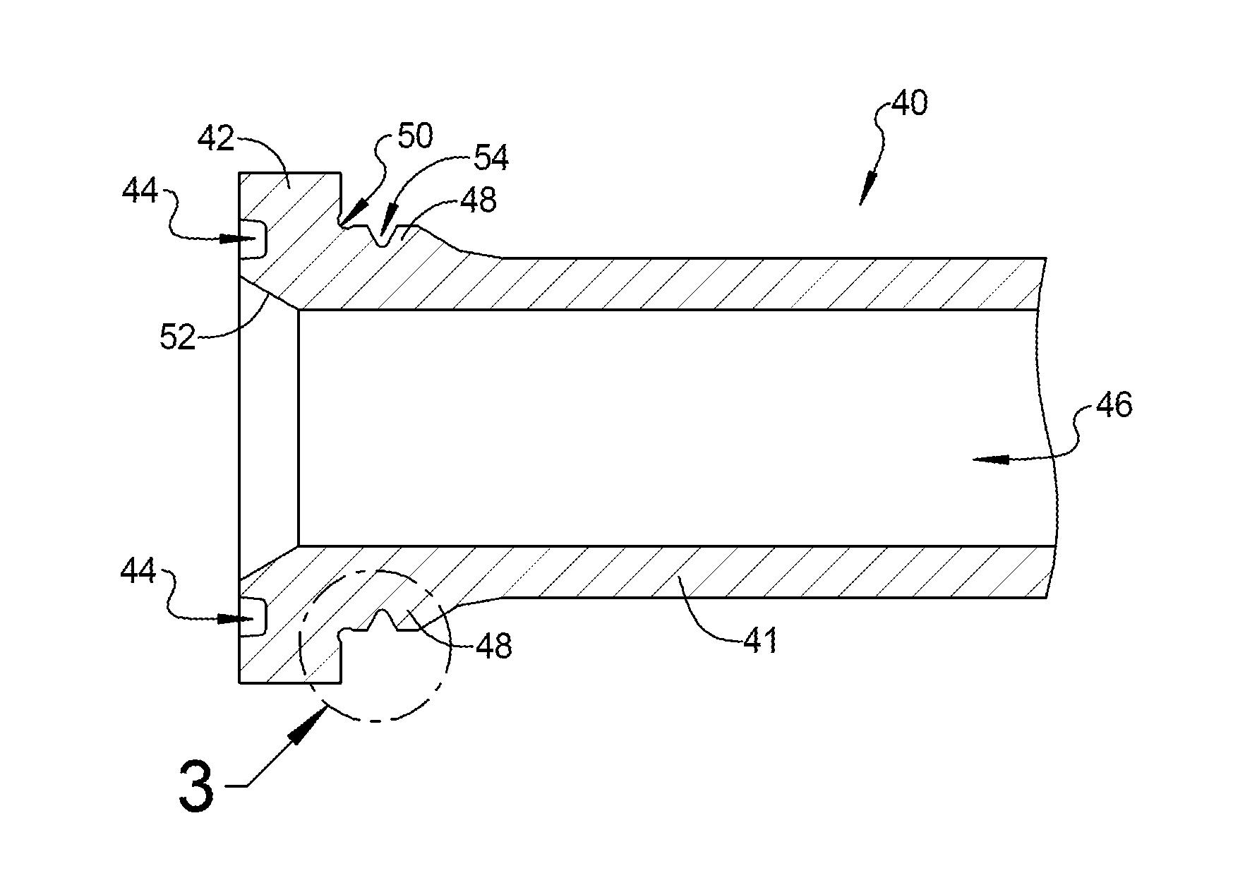
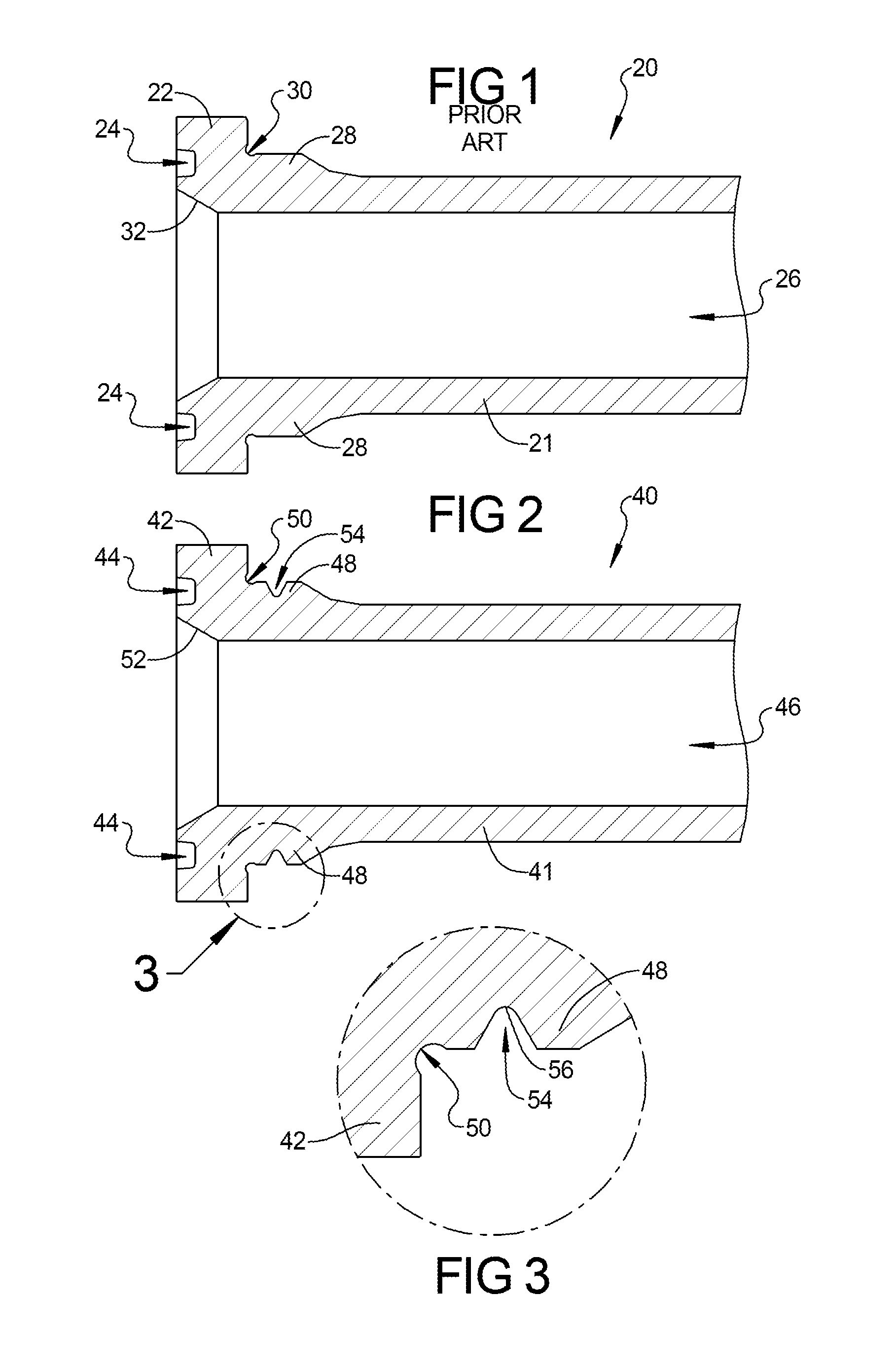
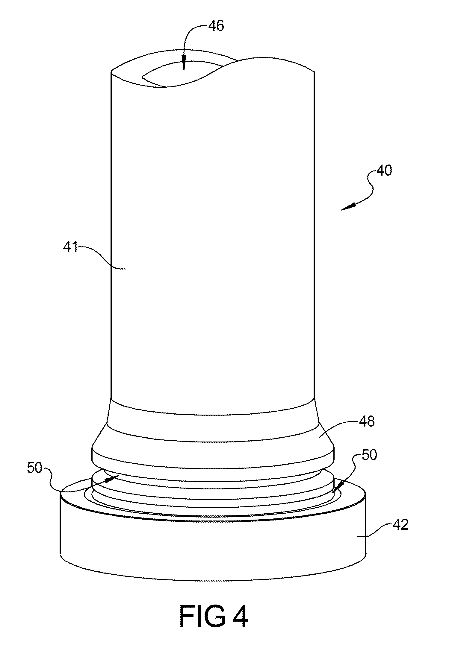
[0005]Specifically, in terms of the structure of this improved flange connector, a circumferential second groove is formed in the flange approximately adjacent to a prior art first groove where in a first embodiment, the second groove is oriented approximately perpendicular to the longitudinal axis of the tube that is joined to and extends from the flange connector. The second groove significantly reduces the bending stresses in the section of the flange connector know as the flange section and specifically at the areas where there is a change in cross-sectional area. The circumferential first groove acts to reduce the stresses at that point where the cross-sectional area changes from that of the flange section to the transition section. However, the stresses can be further reduced with the introduction of this second groove in the transition section. The first groove is substantially circular in profile at its root while in the first embodiment, the second groove is shown as a “V” shaped groove.
[0007]In a second alternative embodiment, the circumferential second groove is enlarged still further and the second groove is given a relatively larger radius to further lower the stress levels as compared to the prior art. The radius of the second groove for this second alternative embodiment is approximately one half the radius of the tube section.
[0008]Other shapes of either / or the first and second groove can be varied as necessary to facilitate manufacturing and to minimize the stresses in the flange connector to improve performance and packaging.

Problems solved by technology

The high hydraulic pressures handled by this type of connector necessarily includes pressure waves that increase the stress levels within the flanged connector that reduce the operational life of the connector.
Also, mechanically induced bending loads which can result in cyclic fatigue and eventual failure.

Method used


Image

  • Hydraulic flange connection
  • Hydraulic flange connection
  • Hydraulic flange connection

Examples


Embodiment Construction

[0016]Referring now to the discussion that follows and also to the drawings, illustrative approaches to the disclosed systems and methods are shown in detail. Although the drawings represent some possible approaches, the drawings are not necessarily to scale and certain features may be exaggerated, removed, or partially sectioned to better illustrate and explain the present disclosure. Further, the descriptions set forth herein are not intended to be exhaustive or otherwise limit or restrict the claims to the precise forms and configurations shown in the drawings and disclosed in the following detailed description.

[0017]Moreover, a number of constants may be introduced in the discussion that follows. In some cases illustrative values of the constants are provided. In other cases, no specific values are given. The values of the constants will depend on characteristics of the associated hardware and the interrelationship of such characteristics with one another as well as environmenta...


PUM


Abstract

A hydraulic flange connection formed on a tube having a first groove formed in the outside of the flange at a first stress area and a second groove formed in the outside surface of the flange at a secondary stress area and extending in a direction substantially perpendicular to a central cavity formed in the tube.

Description

FIELD OF THE INVENTION[0001]The present hydraulic flange connection relates to a mechanical flanged connection primarily used in connection of a high pressure hydraulic line to a prime operator such as a hydraulic motor, pump or valve assembly. A circumferential secondary groove is located in an outside surface of the flange positioned to reduce the operational stresses of the flange connector thereby increasing its operational life.BACKGROUND OF THE INVENTION[0002]Mechanical connections are used to connect high pressure hydraulic sources to prime movers such as a pump, motor or a valve assembly. One type of connector used in these applications is what is known as a flange. The Society of Automotive Engineers, through Standard J518, and the International Organization for Standardization, through standard 6162, have standardized on a flanged connector under the industry names of Code 61 or Code 62. The high hydraulic pressures handled by this type of connector necessarily includes pr...

Claims


Application Information

Patent Timeline
IPC IPC(8): F16L23/00
CPCF16L23/032F16L23/0283
Inventor RAJOPADHYE, KAPIL V.
Owner EATON CORP
Learn More