
Flow Sensing Dual Pump Switching System and Method

Active Publication Date: 2012-06-21
WOODWARD GOVERNOR CO
View PDF4 Cites 12 Cited by
  • Summary
  • Abstract
  • Description
  • Claims
  • Application Information

AI Technical Summary

Benefits of technology

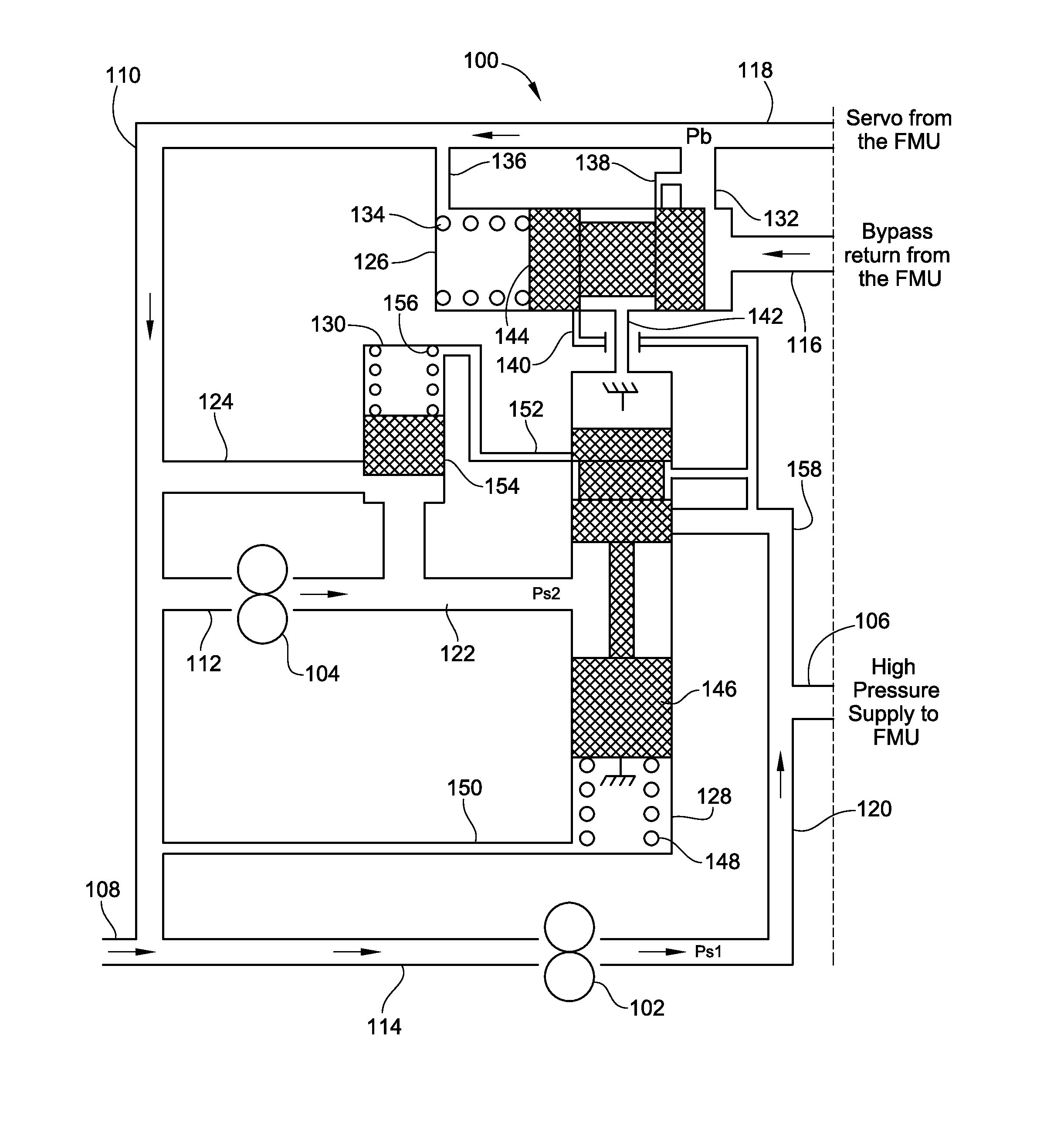
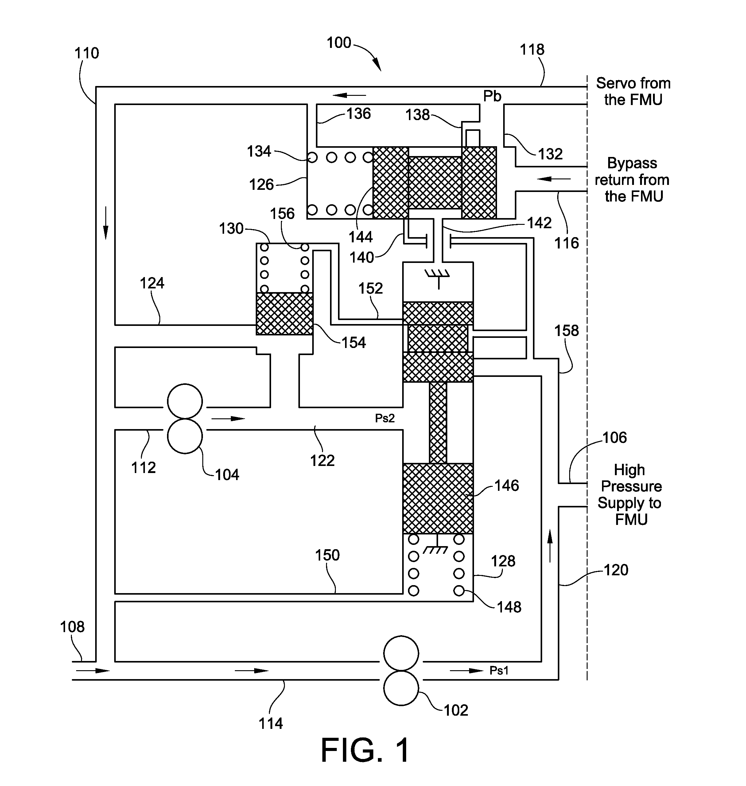
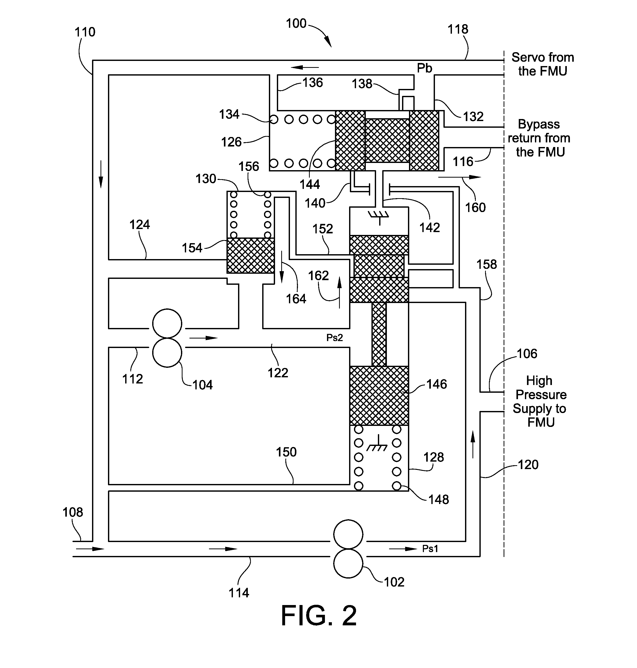
[0007]In view of the above, embodiments of the present invention provide a new and improved dual pump fuel supply system that reduces or overcomes one or more of the problems existing in the art. More particularly, embodiments of the present invention provide a new and improved dual pump fuel supply system for an aircraft turbine engine that includes a dual pump switching system to reduce the engine burn flow disturbances associated with transitions between pumping modes. Still more particularly, embodiments of the present invention provide a new and improved dual pump fuel supply switching system that utilizes the fuel bypass return from the fuel metering unit to regulate the amount of flow supplied from the dual pump system to the fuel metering unit such that adequate fuel flow is supplied to the engine to meet its operating demands while reducing the engine burn flow disturbances known to exist in prior dual pump fuel supply systems.
[0009]In one embodiment, based on the position of the flow sensing valve, the flow sharing or pump switching valve supplies a portion of the second pump flow to the high pressure supply to the fuel metering unit, in addition to the flow from the first pump, in order to meet the engine flow demand during high fuel demand operating modes. Alternatively, the flow sharing or pump switching valve bypasses the total output flow of the second pump at a low pressure back to the inlet of that pump to minimize the thermal rise otherwise resulting from a high bypass flow situation.
[0010]Embodiments of the dual pump switching system of the present invention allow the discharge flow from the two pumps to be separated when operating in a single pump mode, and then combined when operating in a dual pump mode. In a single pump mode, the first pump supplies all high pressure burn flow to be used by the combustor. Other required engine flows can be supplied by either of the two pumps depending on how the fuel system is configured without effect on the operation of the main fuel supply to the combustor. With an embodiment of the present invention operating in a single pump mode, the discharge pressure of pump one is set by the downstream restrictions, including fuel nozzle restrictions and the combustor pressure. The second pump discharge pressure can be controlled independently of that of the first pump discharge pressure. In this embodiment, the system thermal benefit and reduction in power input comes from minimizing the pressure differential across the second pump when operating in a single pump mode. When the engine flow demand approaches the capacity of the first pump, the second pump pressure is raised above that of the first pump pressure, and a portion of the fuel flow from the second pump is supplied to supplement that from the first pump.
[0011]In an embodiment of the present invention, the bypass flow of fuel from the fuel metering unit is used to control the pressurization of the secondary pump. In a first mode a reduction in the bypass flow from the fuel metering unit will increase the pressure differential of the second pump. This will allow its output to be available to supplement that of the first pump as the engine demand for fuel increases beyond that supplied by the first pump. In a second mode an increase in the bypass return from the fuel metering unit will decrease the pressure differential across the secondary pump to minimize energy consumption during periods of low fuel demand from the engine which can adequately be supplied by the first fuel pump. The pressurization of the second pump in one embodiment is used to control the amount of the second pump flow that is added to that of the first pump, while other embodiments utilize the fuel bypass flow from the fuel metering unit to control same.

Problems solved by technology

Unfortunately, raising the pressure of the excess fuel flow and returning that excess flow back to the low pressure inlet of the pump effectively wastes the energy that had been added to the fuel as it was supplied to the turbine engine.
This wasted energy is realized as a heat input into the fuel, and often results in undesirably high fuel temperatures in some operating conditions.
While such typical dual pump fuel supply systems have addressed the thermal increase issue common with the use of a single high pressure positive displacement fuel pump, the addition of the fuel flow from the second fuel pump to that of the first often results in engine burn flow disturbances that are associated with the switch between the pumping modes.
In modern high efficiency turbine engines, such burn flow disturbances are unacceptable.
While some of these systems have met with success, each require additional control signals from the engine control unit, fuel metering unit, or other components within the overall turbine engine control system.
This increases the complexity, and therefore reduces the reliability, of the overall system.

Method used


Image

  • Flow Sensing Dual Pump Switching System and Method
  • Flow Sensing Dual Pump Switching System and Method
  • Flow Sensing Dual Pump Switching System and Method

Examples


Embodiment Construction

[0021]Turning now to the drawings, there is illustrated in FIG. 1 a schematic illustration of one embodiment of a flow sensing dual pump switching system constructed in accordance with the teachings of the present invention. As illustrated, this embodiment is particularly well suited for application to an aircraft turbine engine. As such, the following will provide a description of the operation of this and other embodiments of the present invention in such an operating environment. However, it should be noted that other applications for a flow sensing dual pump switching system and a dual pump fluid supply system utilizing same are foreseen, and therefore the operating environment discussed below should be taken by way of example and not by way of limitation.

[0022]For the embodiments of flow sensing dual pump switching system discussed hereinbelow, each embodiment is shown in conjunction with a dual pump fluid (fuel) supply system that includes a first pump 102 and a second pump 10...


PUM


Abstract

A flow sensing dual pump switching system and method are provided that control the supply of fuel from a dual pump fuel system to a fuel metering unit. The system senses bypass pressure from the fuel metering unit to control the differential pressurization of the second pump. As the bypass is reduced, the pressure of the second pump is increased so that it may be added to that of the first pump to supply the increased fuel consumption needs of an engine. As the fuel consumption needs decrease, the flow from the second pump added to the first pump is reduced and the differential pressure of the second pump is similarly reduced. If the bypass pressure remains high, the switching system disconnects the output of the second pump from that of the first in favor of bypassing the flow to its input to reduce its differential pressure and conserve energy.

Description

FIELD OF THE INVENTION[0001]The present invention relates generally to aircraft engine fuel control systems, and more particularly to aircraft engine fuel control systems that utilize a dual pump fuel control system for supplying fuel to the aircraft engine over widely varying fuel supply needs.BACKGROUND OF THE INVENTION[0002]The primary function of a fuel supply system is to provide a sufficient flow of fuel to an engine to meet its operating demands. In continuous combustion engines, such as those typically used in a turbine aircraft engine, the fuel supply system typically employs high pressure positive displacement fuel pumps. Such high pressure positive displacement fuel pumps are typically driven via a gear box coupled to the main turbine engine. As such, the pump flow rate in such a fuel supply system is directly proportional to the engine speed, i.e. the greater the speed of the turbine engine, the greater the fuel flow rate from the high pressure positive displacement fuel...

Claims


Application Information

Patent Timeline
IPC IPC(8): F04B49/035F02C7/236F04B23/04
CPCF04B23/04F02C7/236F05D2270/3015F02C7/232F02C9/263F05D2260/606
Inventor BAKER, CARTHEL C.BARYSHNIKOV, DMITRIY
Owner WOODWARD GOVERNOR CO
Learn More