
Fan and motor assembly and method of assembling

a technology of motors and parts, applied in the field of motors, can solve problems such as negative affecting the overall performance of the fan, and achieve the effects of reducing airflow restriction and flow disturban

Active Publication Date: 2014-07-24
REGAL BELOIT AMERICA
View PDF7 Cites 7 Cited by
  • Summary
  • Abstract
  • Description
  • Claims
  • Application Information

AI Technical Summary

Benefits of technology

The patent describes a motor assembly that includes a fan housing with an air inlet and an air outlet, and a motor positioned within the fan housing. The motor includes a first end, a second end, and a shaft. The motor assembly also includes a fan coupled to the shaft, and at least one mounting arm coupled to the motor and the fan housing. The mounting arm has a streamlined body with a first stagnation point, a second end, and a plurality of points along a surface of the streamlined body. Each point of the plurality of points has a coefficient of pressure less than 1, and the streamlined body is configured to direct air around the at least one mounting arm to reduce airflow restriction and flow disturbance within the fan housing. The patent also describes a method of assembling the motor assembly. The technical benefit of the motor assembly is to reduce airflow restriction and flow disturbance within the fan housing, which improves the performance of the motor.

Problems solved by technology

However, some known motors and / or their mounting components restrict entering and exiting air and produce aerodynamic losses that negatively affect the overall performance of the fan.

Method used


Image

  • Fan and motor assembly and method of assembling
  • Fan and motor assembly and method of assembling
  • Fan and motor assembly and method of assembling

Examples


Embodiment Construction

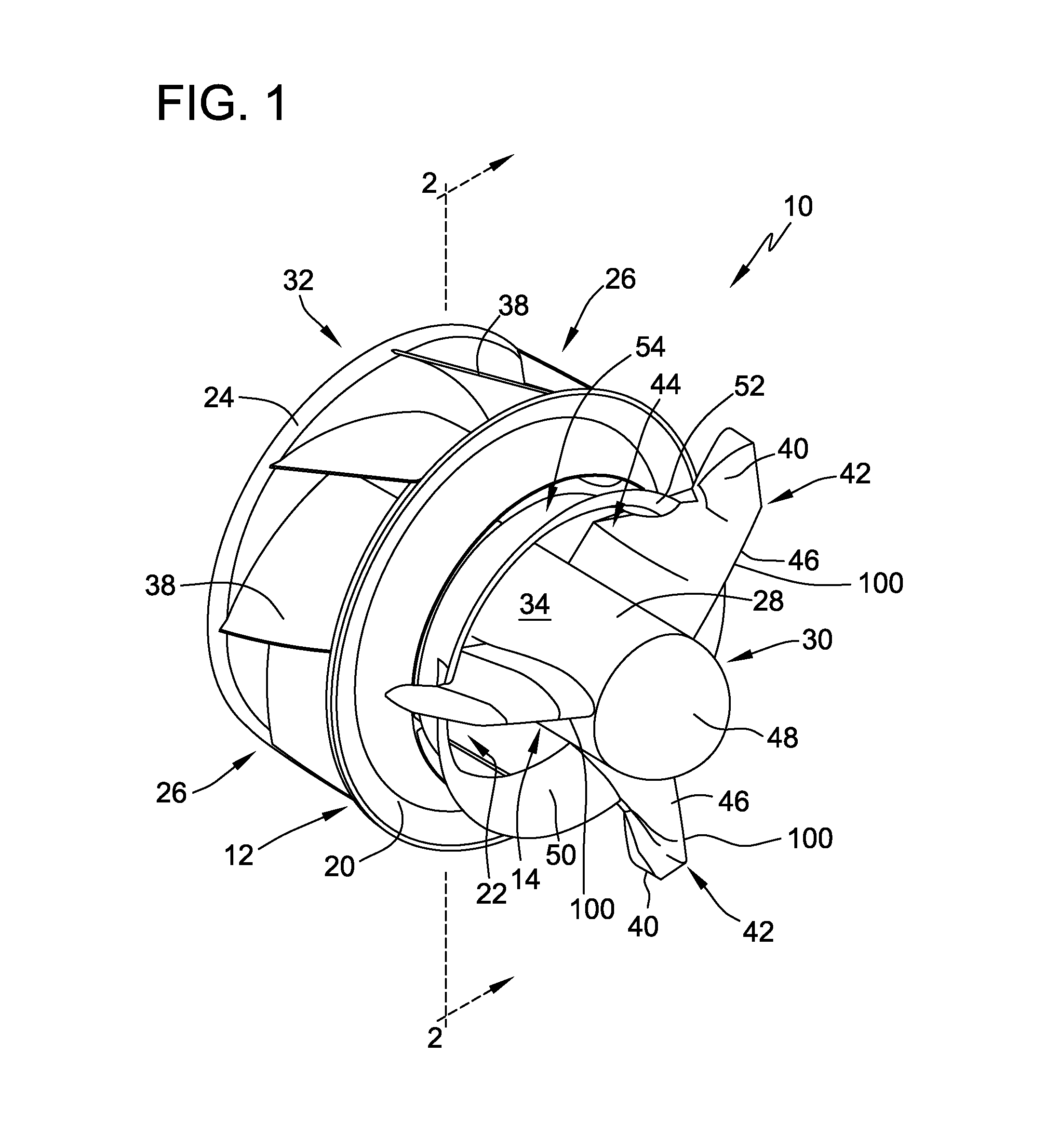
[0013]The present disclosure provides an exemplary fan and motor assembly with an aerodynamic structural design that improves air flow over the assembly, air flow entering the fan, and downstream of the fan. More specifically, the exemplary fan and motor assembly includes a contoured motor housing, contoured mounting brackets, and an inlet guide vane that each reduce airflow restriction and downstream disturbances in the airflow, which results in increased efficiency and a more favorable and laminar airflow into the fan, thereby improving fan and system efficiency.

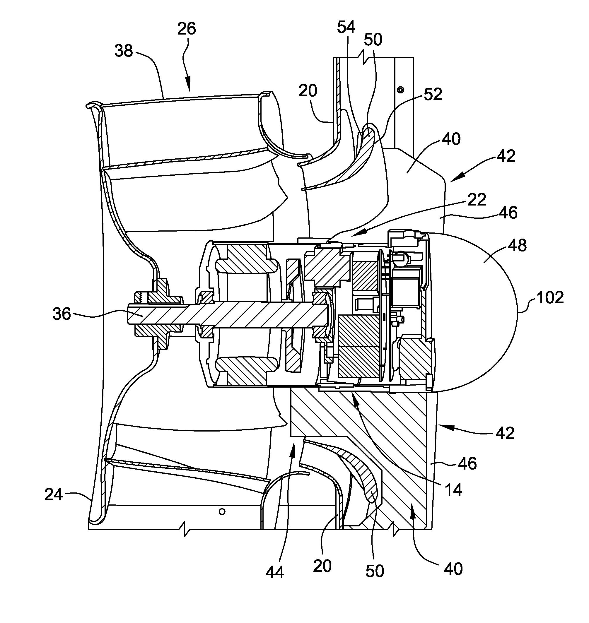
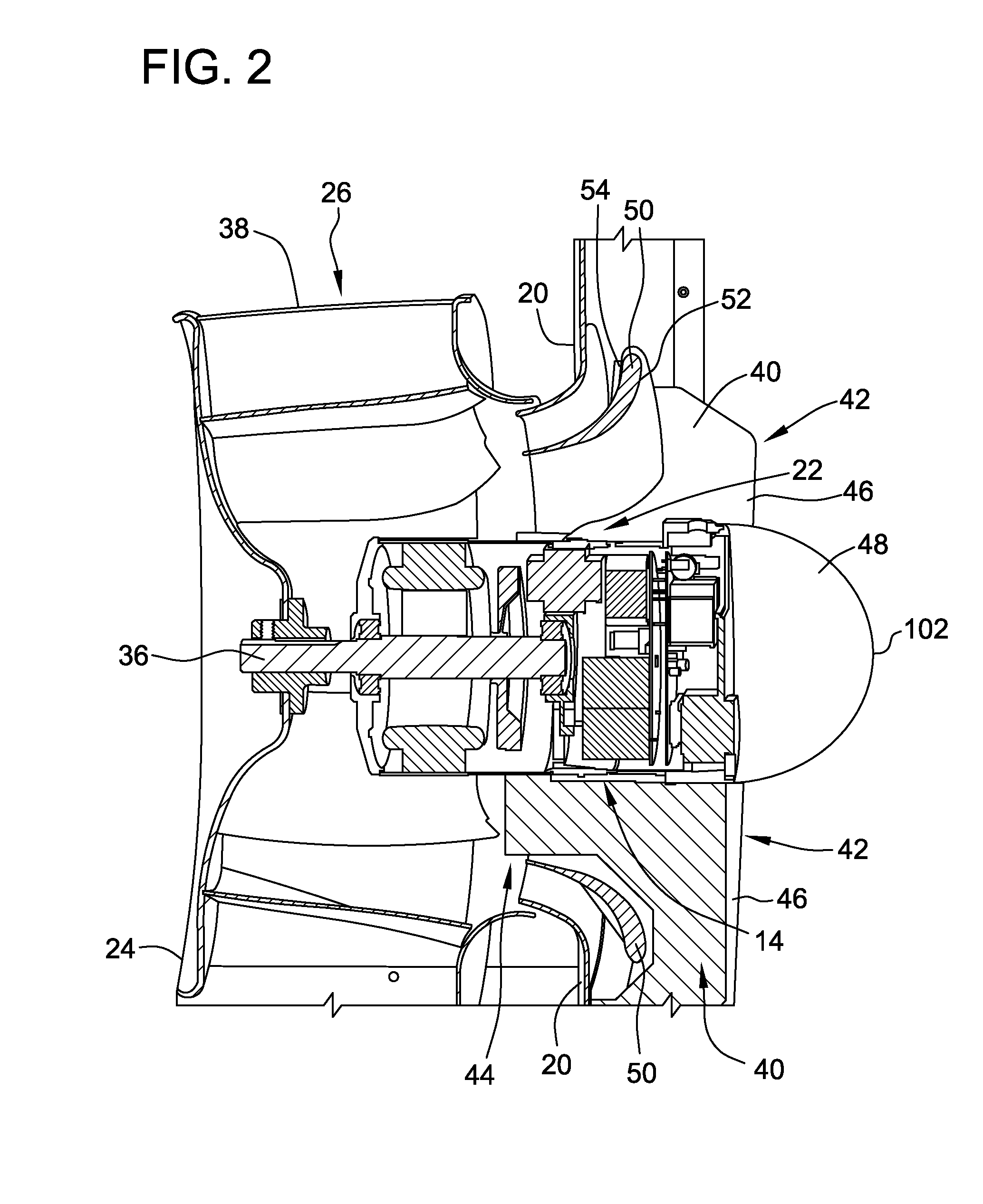
[0014]FIGS. 1-3 illustrate an exemplary embodiment of a fan and motor assembly 10 including a fan housing 12, a motor 14, and a fan 16. Fan housing 12 includes a first end 20 and a second end 24. In the exemplary embodiment, fan housing 12 is a centrifugal fan housing with an air inlet 22 defined by first end 20, and an air outlet 26 defined circumferentially between first and second ends 20 and 24. Alternatively, second e...


PUM

PropertyMeasurementUnit
coefficient of pressureaaaaaaaaaa
pressureaaaaaaaaaa
aerodynamic lossesaaaaaaaaaa

Abstract

In one aspect, a motor assembly is provided. The motor assembly includes a fan housing having an air inlet and an air outlet, and a motor coupled to the fan housing and positioned within the air inlet. The motor includes a first end, a second end, and a shaft. The motor assembly further includes a fan coupled to the shaft proximate the motor second end. The motor first end includes a contoured surface having a stagnation point and a plurality of points along the contoured surface downstream of the stagnation point. Each point of the plurality of points has a coefficient of pressure less than 1, and the contoured surface is configured to direct air around the motor and to reduce airflow restriction and flow disturbance within the fan housing

Description

BACKGROUND[0001]The field of the disclosure relates generally to motors and, more specifically, to fan motor assemblies for use in forced air or air circulating systems.[0002]Many known residential and commercial forced air, heating and air conditioning systems require air propulsion units. In addition to providing movement of air for heating and cooling systems, air propulsion units are often used in combination with condenser units or to supplement other heat transfer operations. Some known air propulsion units are motor driven fans. These fans may be, for example, a blower wheel type or a multi-bladed type. However, some known motors and / or their mounting components restrict entering and exiting air and produce aerodynamic losses that negatively affect the overall performance of the fan.BRIEF DESCRIPTION[0003]In one aspect, a motor assembly is provided. The motor assembly includes a fan housing having an air inlet and an air outlet, and a motor coupled to the fan housing and posi...

Claims


Application Information

Patent Timeline
Patent Type & Authority Applications(United States)
IPC IPC(8): F04D19/00F04D29/64
CPCF04D29/644F04D19/002F04D17/16F04D25/0606F04D29/4213F04D29/441F04D29/626F05D2250/51Y10T29/49245
Inventor COCKS, RACHELE BARBARAKLEIST, MATTHEW JAMESSTAUFFER, ZACHARY JOSEPH
Owner REGAL BELOIT AMERICA
Learn More