Optical body, window member, fitting, solar shading device, and building

a technology for solar shading and optical bodies, applied in the direction of optical elements, instruments, synthetic resin layered products, etc., can solve the problems of just specular reflection, insufficient shielding ability of pigment layers, and acceleration of phenomena, so as to improve safety, reduce heat generation, and save energy

Active Publication Date: 2012-06-21
DEXERIALS CORP
View PDF6 Cites 20 Cited by
  • Summary
  • Abstract
  • Description
  • Claims
  • Application Information

AI Technical Summary

Benefits of technology

[0008]The above-described optical body can retro-reflectively reflect the incident light by reflecting the incident light three times with the wavelength selective reflecting layer. However, because the number of times of reflections is large, the wavelength selective reflecting layer absorbs light in amount about three times that absorbed by a flat plate and an amount of generated heat increases. Accordingly, when the above-described optical body is used as a film for a window, people feel hot with air in a space near the window and an air conditioner is operated at a higher utilization rate, whereby an amount of CO2 omission is increased.
[0025]In the optical body of the present invention, the concave-convex surface is formed by arraying asymmetrical triangular pillars in a one-dimensional pattern, and the wavelength selective reflecting layer is formed on the concave-convex surface. Accordingly, when the optical body of the present invention is applied to an adherend such as a window member, it can reflect the light in the particular wavelength band upward while transmitting light other than the particular wavelength band therethrough. Also, when the optical body of the present invention is applied to, e.g., a window member of a building, it can directionally reflect the light in the particular wavelength band to be kept from entering a predetermined space inside the building, for example, while allowing the light other than the particular wavelength band to be taken into the predetermined space.
[0027]According to the present invention, as described above, in the optical body capable of reflecting the light in the particular wavelength band while transmitting the light other than the particular wavelength band therethrough, an improvement in safety and energy saving can be realized by reducing heat generation attributable to absorption of the light. Further, a high upward reflectance can be obtained.

Problems solved by technology

However, those reflecting layers are formed on a flat window glass, and they can just specularly reflect the incident sunlight.
Such a local temperature rise causes the problems that, in urban areas, a heat island phenomenon is accelerated, and that the lawn grass does not grow only in areas irradiated with the reflected light.
This raises the problems that the shield ability of the pigment layer is insufficient, and that the glass may be cracked due to thermal stress.
Further, there is another problem that the pigment layer is poor in weatherbility and is less convenient when used in high-rise buildings in which frequent replacement of the pigment layer is difficult.

Method used


Image

  • Optical body, window member, fitting, solar shading device, and building
  • Optical body, window member, fitting, solar shading device, and building
  • Optical body, window member, fitting, solar shading device, and building

Examples


first embodiment

1. First Embodiment

[Construction of Optical Film]

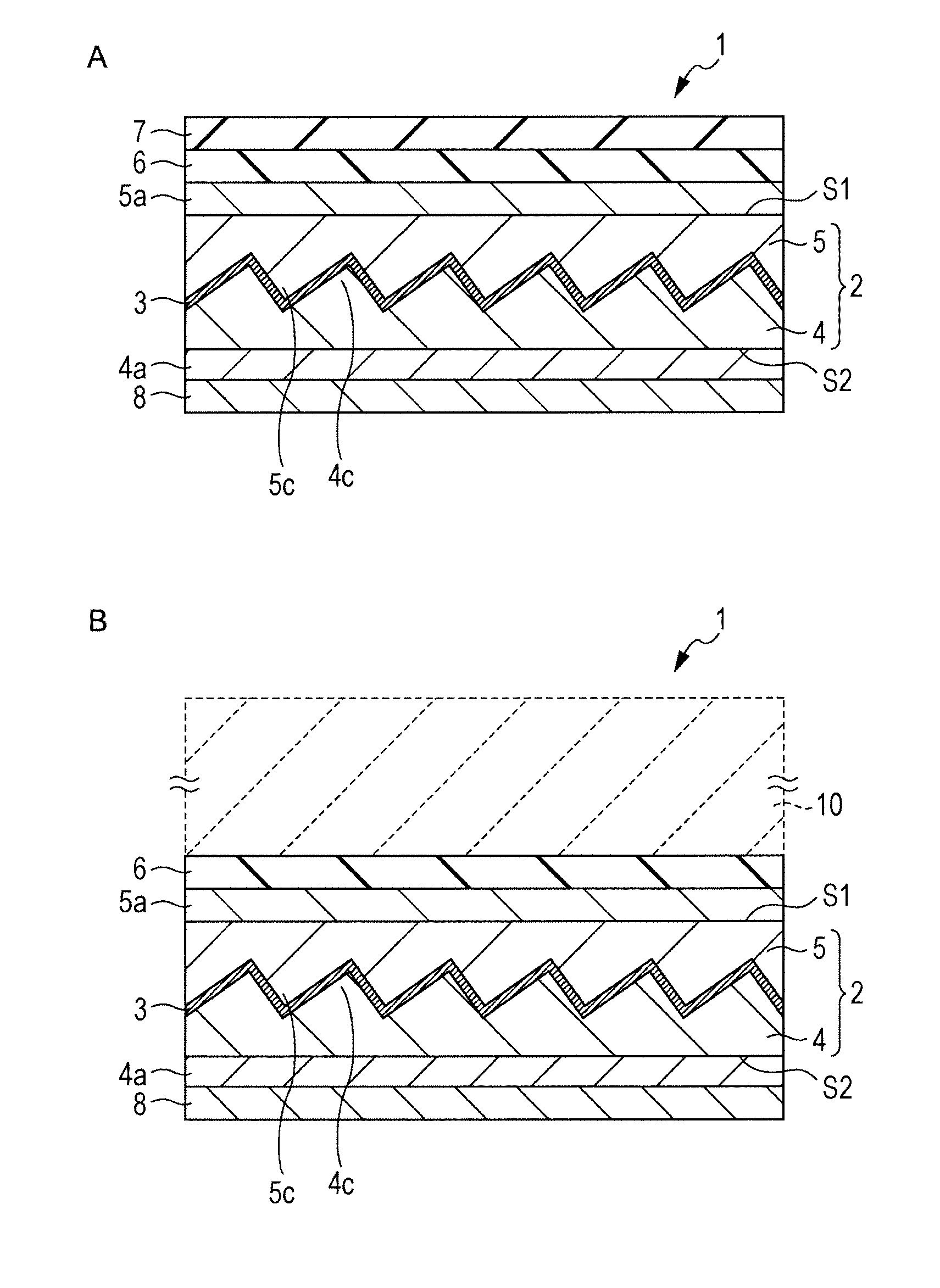
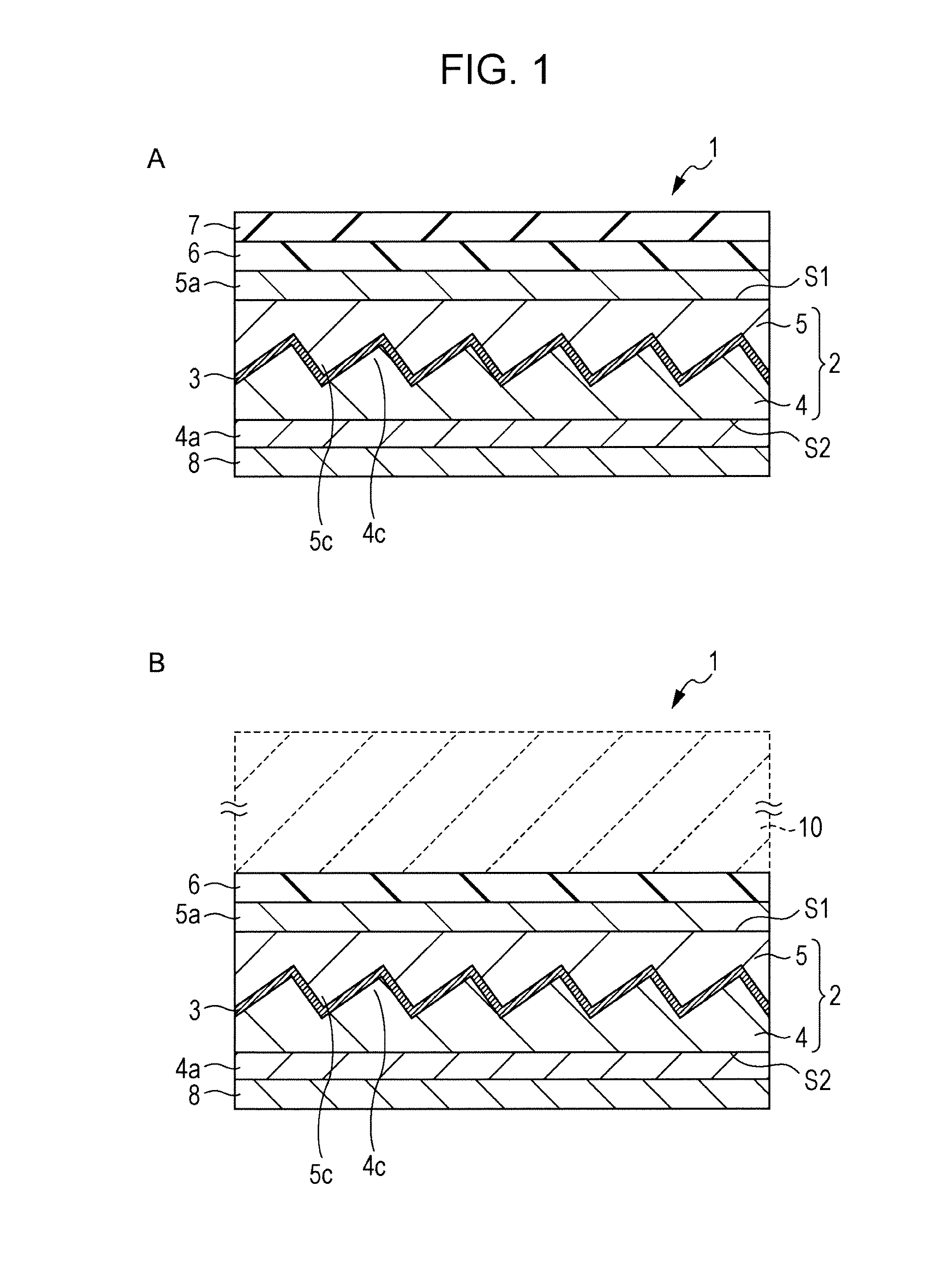
[0068]FIG. 1A is a sectional view illustrating one example of construction of an optical film according to a first embodiment. FIG. 1B is a sectional view illustrating an example in which the optical film according to the first embodiment is affixed to an adherend. An optical film 1 as an optical body is an optical film having the so-called directional reflection property. As illustrated in FIG. 1A, the optical film 1 includes an optical layer 2 having an interface formed therein in a concave-convex shape, and a wavelength selective reflecting layer 3 formed at the interface in the optical layer 2. The optical layer 2 includes a first optical layer 4 having a first surface in a concave-convex shape, and a second optical layer 5 having a second surface in a concave-convex shape. The interface in the optical layer is formed by the first surface and the second surface each having the concave-convex shape, which are arranged to face each ...

first modification

[0172]FIG. 11A is a sectional view illustrating a first modification of the first embodiment. As illustrated in FIG. 11A, an optical film 1 according to the first modification has an incident surface S1 in a concave-convex shape. The concave-convex shape of the incident surface S1 is formed to follow the concave-convex shape of the first optical layer 4, for example, such that positions of top portions of convexes and positions of bottom portions of concaves are aligned between both the concave-convex shapes. The concave-convex shape of the incident surface S1 is preferably gentler than that of the first optical layer 4.

second modification

[0173]FIG. 11B is a sectional view illustrating a second modification of the first embodiment. As illustrated in FIG. 11B, an optical film 1 according to the second modification is formed such that top portions of convexes in the concave-convex surface of the first optical layer 4, on which the wavelength selective reflecting layer 3 is formed, are substantially flush with the incident surface S1 of the first optical layer 4.


PUM

PropertyMeasurementUnit
Angleaaaaaaaaaa
Angleaaaaaaaaaa
Lengthaaaaaaaaaa

Abstract

An optical body includes a first optical layer having a concave-convex surface, a wavelength selective reflecting layer formed on the concave-convex surface, and a second optical layer formed on the wavelength selective reflecting layer and embedding the concave-convex surface. The wavelength selective reflecting layer selectively directionally reflects light in a particular wavelength band while transmitting light other than the particular wavelength band therethrough. The concave-convex surface is made up of a plurality of triangular pillars arrayed in a one-dimensional pattern, and the triangular pillar has an apex angle α and a slope angle β, the apex angle α and the slope angle βsatisfying a predetermined relationship.

Description

TECHNICAL FIELD[0001]The present invention relates to an optical body, a window member, a fitting, a solar shading device, and a building. More particularly, the present invention relates to an optical body for directionally reflecting incident light.BACKGROUND ART[0002]Recently, cases of coating a layer, which partly absorbs or reflects the sunlight, on architectural glasses for high-rise buildings and housings, vehicular window glasses, etc. have increased. Such a trend represents one of energy-saving measures with the view of preventing global warming, and it is intended to reduce a load of cooling equipment, which is increased with optical energy incoming from the sun, entering the indoor through windows, and raising the indoor temperature. The optical energy incoming with the sunlight is primarily provided in a visible range at wavelengths of 380 to 780 nm and in a near infrared range at wavelengths of 780 to 2100 nm. Because transmittance of light in the latter near infrared r...

Claims


Application Information

Patent Timeline
IPC IPC(8): G02B27/14
CPCB32B7/12B32B27/08B32B27/36B32B2255/10B32B2255/26G02B5/282C03C2217/77G02B5/045G02B5/208G02B5/23G02B5/26B32B2307/416
Inventor YOSHIDA, HIRONORINAGAHAMA, TSUTOMUENOMOTO, MASASHI
Owner DEXERIALS CORP
Why Eureka
Try Eureka